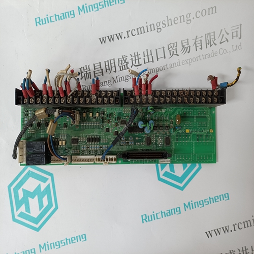
Home > Product > DCS control system > 5X00063G01 Ovation analog module
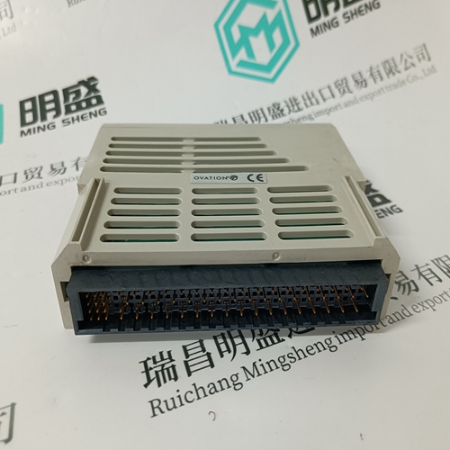
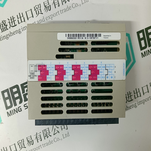
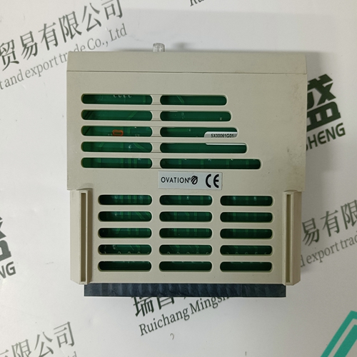
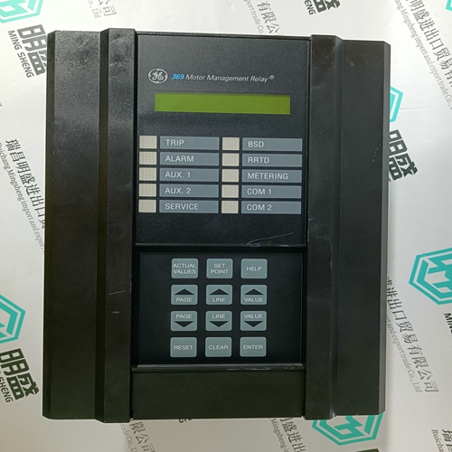
5X00063G01 Ovation analog module
- Product ID: 5X00063G01
- Brand: EMERSON
- Place of origin: The United States
- Goods status: new/used
- Delivery date: stock
- The quality assurance period: 365 days
- Phone/WhatsApp/WeChat:+86 15270269218
- Email:stodcdcs@gmail.com
- Tags:5X00063G01Ovation analog module
- Get the latest price:Click to consult
The main products
Spare parts spare parts, the DCS control system of PLC system and the robot system spare parts,
Brand advantage: Allen Bradley, BentlyNevada, ABB, Emerson Ovation, Honeywell DCS, Rockwell ICS Triplex, FOXBORO, Schneider PLC, GE Fanuc, Motorola, HIMA, TRICONEX, Prosoft etc. Various kinds of imported industrial parts
5X00063G01 Ovation analog module
• POSITIVE/NEGATIVE REAL POWER DELAY: If the positive/negative real power equals or exceeds the POSITIVE/NEGATIVE REAL POWER LEVEL setpoint value for the time delay programmed in this setpoint, an excessive positive/negative real power condition will occur. • POSITIVE/NEGATIVE REACTIVE POWER RELAY: Positive and negative reactive power level detection can either be disabled, used as an alarm, or as a process control. Set this setpoint to “Off” if the feature is not required. Selecting “Alarm” activates the alarm relay and displays an alarm message whenever a positive/negative reactive power level exceeds the selected level. Selecting an auxiliary relay activates the auxiliary relay for a set level of positive/negative reactive power but no message will be displayed. This is intended for process control. • POSITIVE/NEGATIVE REACTIVE POWER LEVEL: When the three phase reactive power equals or exceeds the level set by this setpoint, an excess positive/negative reactive power condition will occur. • POSITIVE/NEGATIVE REACTIVE POWER DELAY: If the positive reactive power equals or exceeds the POSITIVE/NEGATIVE REACTIVE POWER LEVEL setpoint value for the time delay programmed in this setpoint, an excessive positive reactive power condition will occur.
It is generally desirable for a system
operator to maintain the power factor as close to unity as possible (that is, to make the real power of the system as close as possible to the apparent power) to minimize both costs and voltage excursions. On dedicated circuits such as some large motors, with a near-fixed load, a capacitor bank may be switched on or off with the motor to supply leading vars to compensate for the lagging vars required by the motor. Since the power factor is variable on common non-dedicated circuits, it is advantageous to compensate for low (lagging) power factor values by connecting a capacitor bank to the circuit when required. The PQMII provides power factor monitoring and allows two stages of capacitance switching for power factor compensation.Two independent ‘elements’ are available for monitoring power factor, Power Factor 1 and Power Factor 2, each having a pickup and a dropout level. For each element, when the measured power factor is equal to or becomes more lagging than the pickup level (i.e. numerically less than), the PQMII will operate a user-selected output relay. This output can be used to control a switching device which connects capacitance to the circuit, or to signal an alarm to the system operator. After entering this state, when the power factor becomes less lagging than the power factor dropout level, the PQMII will reset the output relay to the non-operated state
