Home > Product > Gas turbine system > GE DS200SVMAG1A Gas turbine DO module

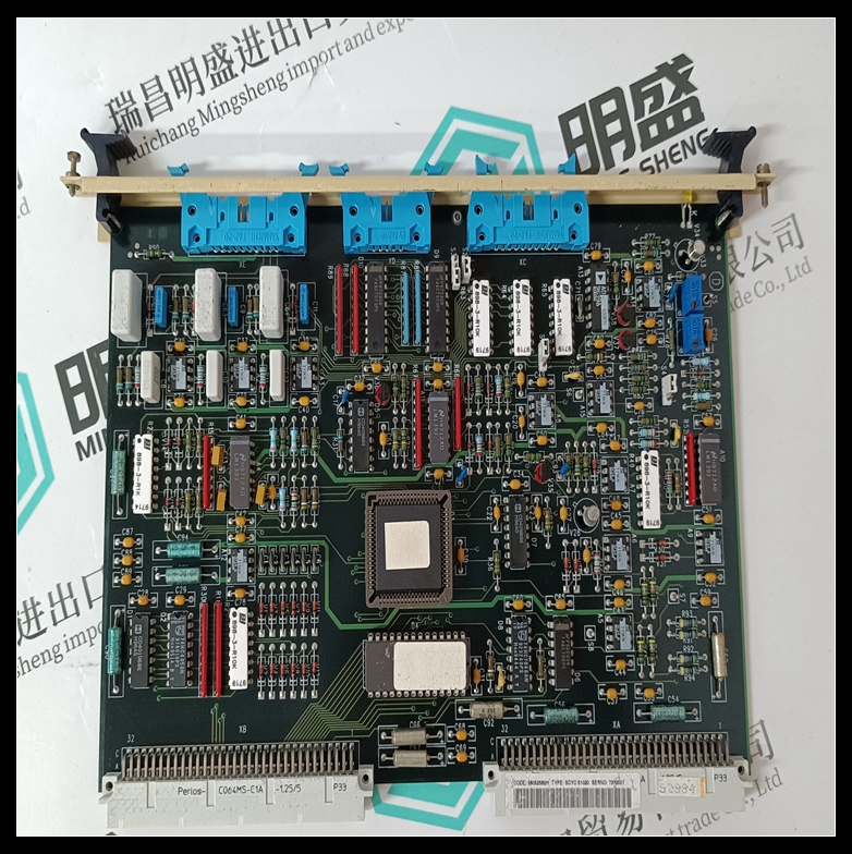
GE DS200SVMAG1A Gas turbine DO module
- Product ID: DS200SVMAG1A
- Brand: GE
- Place of origin: The United States
- Goods status: new/used
- Delivery date: stock
- The quality assurance period: 365 days
- Phone/WhatsApp/WeChat:+86 15270269218
- Email:xiamen2018@foxmail.com
- Tags:GEDS200SVMAG1AGas turbine DO module
- Get the latest price:Click to consult
GE DS200SVMAG1A Gas turbine DO module
Apply power to the drive. 10. Enable the drive. 11. The waveform could be as shown in Figure 5-3. In this case, the system has insufficient dynamic gain. Turn the PROPORTIONAL potentiometer clockwise to obtain a waveform without oscillation. Figure 5-3 Waveform resulting from insufficient proportional gain The minimum acceptable amplitude for the reference signal is 1V peak-to-peak.When a waveform without oscillation has been obtained, in most cases the response will have an overshoot as shown in Figure 5-4. In this case, the system has insufficient derivative action. Turn the DERIVATIVE potentiometer clockwise to eliminate the overshoot as shown in Figure 5-5.It may be necessary to adjust repetitively the PROPORTIONAL and DERIVATIVE potentiometers. If the drive has instability problems after adjustment and when it is connected to a position controller, refer to section 5.7 Commissioning on page 54 and Chapter 6 Diagnostics on page 56.
ZERO REF potentiometer
Connect the non-inverting speed reference signal input to pin 9 and the inverting input to pin 10. 2. Set the speed reference signal for zero speed. 3. Remove the connection from pin 15 (STOP signal). 4. Connect a digital multi meter to pins 11 and 12. 5. Enable the drive and adjust the ZERO REF potentiometer to reduce the multi meter reading to not more than 1mV. 6. Restore the original wiring. If the motor is creeping with a zero speed reference, or when a stop command is applied, please contact the supplier of the drive.
The value of the RT resistor
must be between 2.7kW and 3.9kW. 2. Fit the resistor. 3. Apply a 2V to 10V speed reference signal between pins 9 and 10. (To generate this signal, use the external controller or the reference voltage output on pins 6 and 7). 4. Measure the reference signal applied to pins 9 and 10 and calculate the tachogenerator output value using the following equation:Measure the tachogenerator output voltage with a digital multimeter, and adjust the maximum speed for the multimeter to show the calculated value. Calibration should be optimized using a speed indicator.

Company product range
----------------------Ruichang Mingsheng Automation Equipment Co., Ltd----------------------
PLC module, programmable controller, CPU module, IO module, DO module, AI module, DI module
Network communication module,
Ethernet module, motion control module, analog input module, analog output module, digital input module, digital output
Module, redundancy module, power module, relay output module, relay input module, processor module