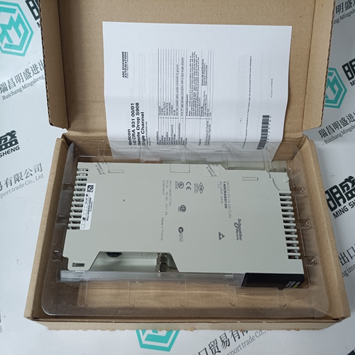
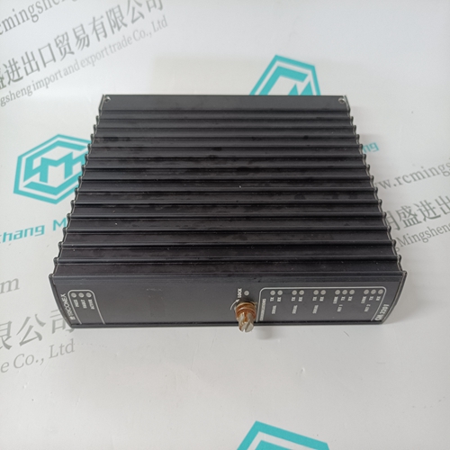
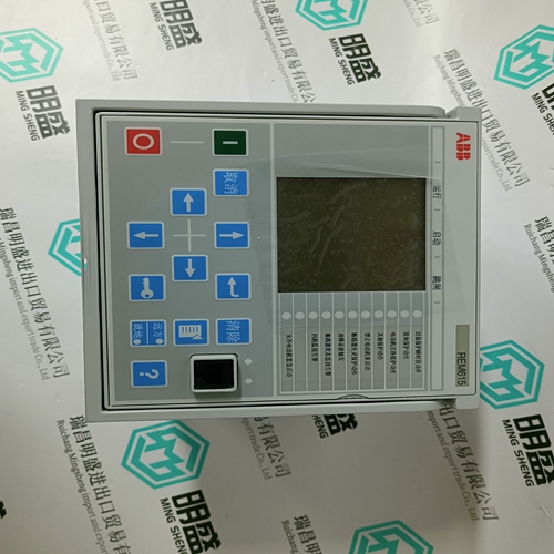
Home > Product > PLC programmable module > Reliance DDS-LPS Interface component module
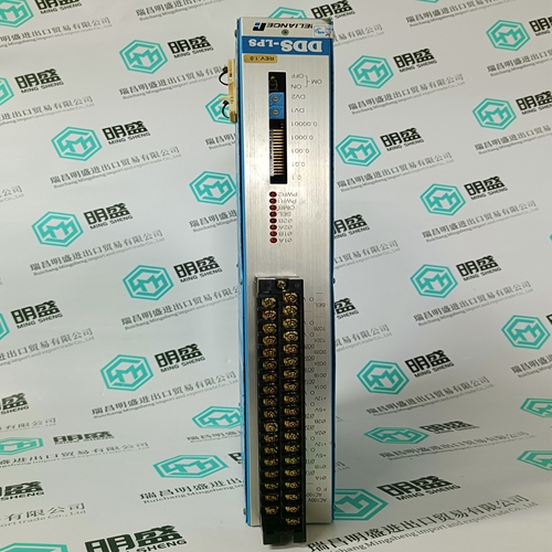
Reliance DDS-LPS Interface component module
- Product ID: DDS-LPS
- Brand: RELIANCE
- Place of origin: the United States
- Goods status: new/used
- Delivery date: stock
- The quality assurance period: 365 days
- Phone/WhatsApp/WeChat:+86 15270269218
- Email:stodcdcs@gmail.com
- Tags:RelianceDDS-LPSInterface component module
- Get the latest price:Click to consult
The main products
Spare parts spare parts, the DCS control system of PLC system and the robot system spare parts,
Brand advantage: Allen Bradley, BentlyNevada, ABB, Emerson Ovation, Honeywell DCS, Rockwell ICS Triplex, FOXBORO, Schneider PLC, GE Fanuc, Motorola, HIMA, TRICONEX, Prosoft etc. Various kinds of imported industrial parts
Reliance DDS-LPS Interface component module
Both Power Factor 1 and 2 features are inhibited from operating unless all three voltages are above 20% of nominal and one or more currents is above 0. Power factor 1 and 2 delay timers will be allowed to time only when the 20% threshold is exceeded on all phases (and, of course, only while the power factor remains outside of the programmed pickup and dropout levels). In the same way, when a power factor condition starts the power factor 1 or 2 delay timer, if all three phase voltages fall below the 20% threshold before the timer has timed-out, the element will reset without operating. A loss of voltage during any state will return both Power Factor 1 and 2 to the reset state. • POWER FACTOR LEAD 1(2) RELAY: Power factor detection can either be disabled, used as an alarm or as a process control. Set this setpoint to “Off” if the feature is not required. Selecting “Alarm” activates the alarm relay and displays an alarm message when the power factor is more leading than the level set. Selecting “Aux1”, “Aux2”, or “Aux3” activates the respective auxiliary relay when the power factor is equal to or more leading than the level set, but no message will be displayed. This is intended for process control. A minimum of 20 V applied must exist on all voltage inputs before this feature will operate. • POWER FACTOR LEAD 1(2) PICKUP: When a leading power factor equals or exceeds the level set by this setpoint, a Power Factor Lead 1(2) condition will occur.
POWER FACTOR LEAD 1(2) DROPOUT
When a leading power factor drops below this level, the Power Factor Lead 1(2) condition will drop out. • POWER FACTOR LEAD 1(2) DELAY: If the power factor equals or exceeds the POWER FACTOR LEAD 1(2) PICKUP setpoint value and remains this way for the time delay programmed in this setpoint, a Power Factor Lead 1(2) condition will occur. If the power factor drops below the POWER FACTOR LEAD 1(2) DROPOUT setpoint value, the power factor lead 1(2) condition will drop out. If the POWER FACTOR LEAD 1(2) RELAY setpoint is set to “Alarm”, the alarm relay will deactivate and the POWER FACTOR LEAD 1(2) ALARM message will be cleared. If the POWER FACTOR LEAD 1(2) RELAY setpoint is set to “Aux1”, “Aux2”, or “Aux3,” the respective auxiliary relay deactivates. • POWER FACTOR LAG 1(2) RELAY: Power factor detection can either be disabled, used as an alarm or as a process control. Set this setpoint to “Off” if the feature is not required. Selecting “Alarm” activates the alarm relay and displays an alarm message when the power factor is more lagging than the level set. Selecting “Aux1”, “Aux2”, or “Aux3” activates the respective auxiliary relay when the power factor is equal to or more lagging than the level set, but no message will be displayed. This is intended for process control. A minimum of 20 V applied must exist on all voltage inputs before this feature will operate. • POWER FACTOR LAG 1(2) PICKUP: When a lagging power factor equals or exceeds the level set by this setpoint, a Power Factor Lag 1(2) condition will occur.
