Home > Product > Gas turbine system > GE DS200PANAH1A Gas turbine channel module
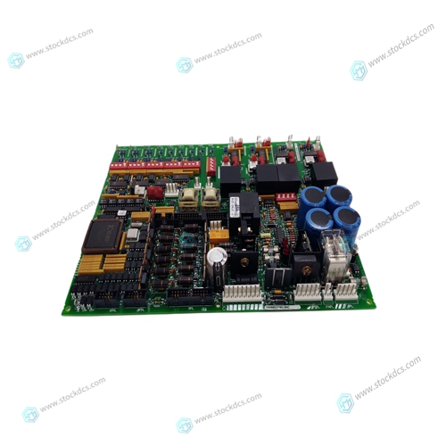
GE DS200PANAH1A Gas turbine channel module
- Product ID: DS200PANAH1A
- Brand: GE
- Place of origin: The United States
- Goods status: new/used
- Delivery date: stock
- The quality assurance period: 365 days
- Phone/WhatsApp/WeChat:+86 15270269218
- Email:stodcdcs@gmail.com
- Tags:GEDS200PANAH1AGas turbine channel module
- Get the latest price:Click to consult
GE DS200PANAH1A Gas turbine channel module
This chapter discusses the mechanical footprint and connectors of the Twisted Pair Control Modules. Details of mounting to an application electronics board are provided.The Twisted Pair Control Modules share a common footprint and connectors as shown in figure 2. The most common control module mounting scenario uses socket strips on the application electronics board which connect with P1 and P2 as shown in figure 3. Vendor information for socket strips that mate with the 0.025" (0.64mm) square header posts of P1 and P2 are referenced in table 5. If necessary, taller socket strips may be used to gain more clearance between the control module and the application board. Decisions about component placement on the application electronics board must also consider electromagnetic interference (EMI) and electrostatic discharge (ESD) issues discussed in Chapter 6 of this document.
Mechanical Footprint
Figures 3A and 3B show the maximum height of parts on both sides of the control modules. Application designs using the transformer-isolated twisted pair transceivers should maintain a minimum of 0.15” (3.81mm) clearance from P2 pins and traces on the network side of the transformer to achieve the minimum isolation specified for these modules. Refer to the High Voltage and EMI Keepout sections in Chapter 6 for isolation requirements. Three plated mounting holes that accept No. 6 (3.5mm) mounting screws are electrically connected to the control module ground plane. When the 0.025" (0.64mm) square posts of P1 and P2 are inserted into the sockets they provide enough holding strength (3 oz (85g)/pin) to secure the control module against shock and vibration to the operating limits of the components on the control module. However, at least one metal standoff and fastening screw located at the mounting hole near the P2 connector is recommended to meet EMI limits and for ESD protection
For the TP/FT-10 control modules
the recommended metal standoff height is 0.56" (14.3mm) to provide adequate clearance. Note that the Methode Socket (referenced in table 3.1) in this case is not recommended, since its minimum insertion depth requirement is not met. Use of metal 0.50" (12.7mm) #6 standoffs together with metal spacers can achieve this. Alternately, metal 0.56" (14.3mm) #6 standoffs alone will be adequate. For the TP/XF, TP/FT-10F, and TP-RS485 control modules, 0.50" (12.7mm) #6 metal standoffs alone are recommended.


Company product range
----------------------Ruichang Mingsheng Automation Equipment Co., Ltd----------------------
PLC module, programmable controller, CPU module, IO module, DO module, AI module, DI module
Network communication module,
Ethernet module, motion control module, analog input module, analog output module, digital input module, digital output
Module, redundancy module, power module, relay output module, relay input module, processor module
