Home > Product > Gas turbine system > GE DS200PCCAG9A Output expansion module
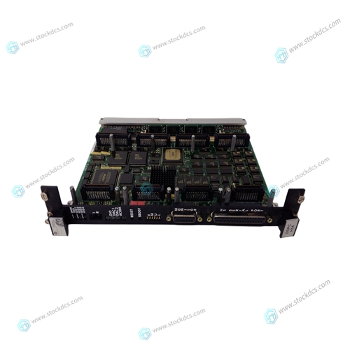
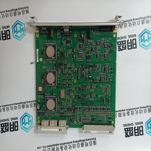
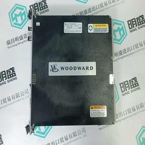
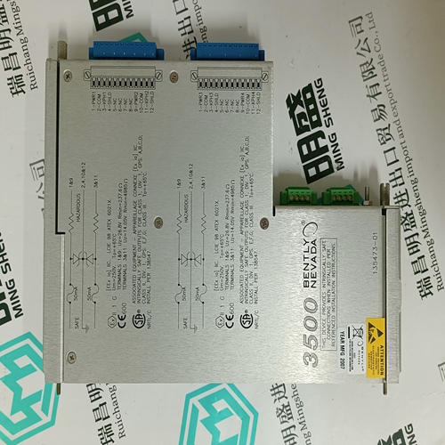
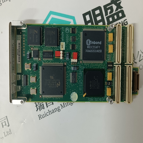
GE DS200PCCAG9A Output expansion module
- Product ID: DS200PCCAG9A
- Brand: GE
- Place of origin: The United States
- Goods status: new/used
- Delivery date: stock
- The quality assurance period: 365 days
- Phone/WhatsApp/WeChat:+86 15270269218
- Email:stodcdcs@gmail.com
- Tags:GEDS200PCCAG9AOutput expansion module
- Get the latest price:Click to consult
GE DS200PCCAG9A Output expansion module
EMC Design Tips • Most of the RF noise originates in the CPU portion of the control module, and in any highfrequency or high-speed application circuitry in the node.
• Most of the EMI will be radiated by the network cable and the power cable.
• Filtering is generally necessary to keep RF noise from getting out on the power cable.
• EMI "Keepout" area restrictions should be observed to prevent internal RF noise from coupling onto the network cable.
• The control module must be well grounded within the node to ensure that its built-in EMI filtering works properly.
Early EMI testing of prototypes at a certified outdoor
range is an extremely important step in the design of level “B” products. This testing ensures that grounding and enclosure design questions are addressed early enough to avoid most last-minute changes (and their associated schedule delays). It is possible for a plastic enclosure to be used with Twisted Pair Control Modules in level “B” applications in some specialized configurations. Since external cables must be kept away from the “RF hot” keepout area on the modules (figure 11), the product configuration must somehow constrain the routing of cables so that they cannot pass across the surface of the plastic enclosure near the module. During FCC EMI testing, cable position is typically varied to generate maximum emission levels (within constraints of normal product usage). The three standoff holes on the control module are generally not needed for mechanical support, but the hole nearest connector P2 is important for EMI grounding of the control module. Best results are achieved by a solid ground connection from the control module to the application mother board and to a metalized enclosure using the P2 standoff.
The Twisted Pair Control Modules
include adequate filtering on the network data communication lines for most node designs to meet level “B” emission limits. In rare cases, such as designs including circuits with extremely fast edges, additional noise attenuation is required. In such cases it may be necessary to use a common-mode choke, such as muRata’s PLT1R53C connected in series with the data communication lines adjacent to the node’s external network connector. This choke will provide an additional 10dB-to-15dB of EMI attenuation over the 30MHz-to-500MHz range. The choke adds a few pF of differential capacitance to the data communication lines, and therefore reduces network performance and may affect introperability. In general, application designs should not require a common-mode choke.


Company product range
----------------------Ruichang Mingsheng Automation Equipment Co., Ltd----------------------
PLC module, programmable controller, CPU module, IO module, DO module, AI module, DI module
Network communication module,
Ethernet module, motion control module, analog input module, analog output module, digital input module, digital output
Module, redundancy module, power module, relay output module, relay input module, processor module
