Home > Product > Gas turbine system > GE DS200PTBAG1A Contact DC module
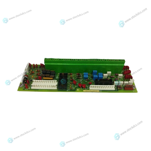
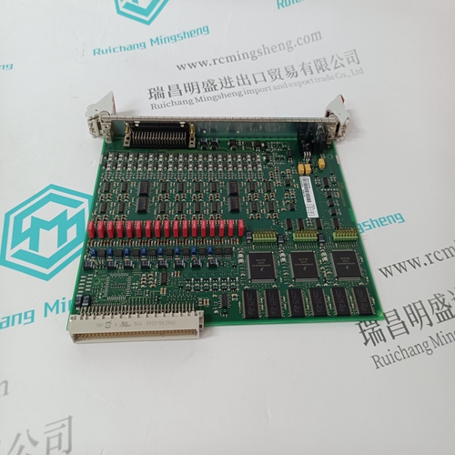
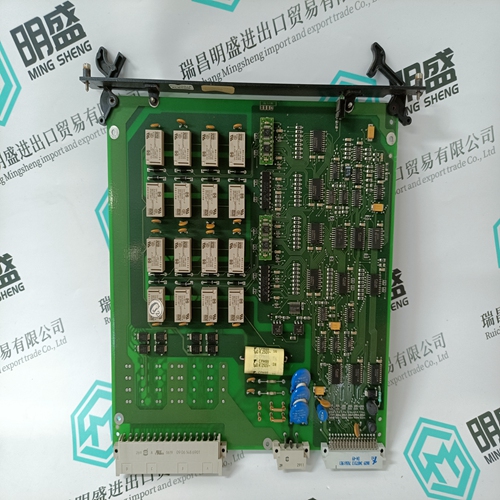
GE DS200PTBAG1A Contact DC module
- Product ID: DS200PTBAG1A
- Brand: GE
- Place of origin: The United States
- Goods status: new/used
- Delivery date: stock
- The quality assurance period: 365 days
- Phone/WhatsApp/WeChat:+86 15270269218
- Email:stodcdcs@gmail.com
- Tags:GEDS200PTBAG1AContact DC module
- Get the latest price:Click to consult
GE DS200PTBAG1A Contact DC module
The TP control modules use diode clamping and transformer isolation to shunt ESD from the network connector P2 to ground. It is therefore important to provide a low impedance ground path from the mounting hole near P2 to the main system ground. The TP/FT-10 also includes spark gaps (designed to arc at approximately 1000 -2000V) between each of the network lines to ground and a diode/capacitor protection circuit to absorb ESD energy. The TP/FT-10F uses similar, but not identical, protection circuitry
Designing for Interoperability
In order to meet the LONWORKS interoperability guidelines regarding TP/XF-78, TP/XF-78F, and TP/XF-1250 nodes, the following printed circuit layout guideline for the application electronics board is recommended. Mutual capacitance of data pair conductors (differential capacitance) from the twisted pair medium tap connector to the connector which mates to the TP/XF control module P2 header must be kept within the maximum limit specified in the table below
Programming Considerations
This section explains the integration of control modules using the LonBuilder Developer’s Workbench and NodeBuilder Development tool. It covers considerations relating to memory specifications, device definition, channel definition, and target emulation hardware.When programming flash memory, the part must be explicitly secured with Software Data Protection (SDP) enabled by the PROM programmer. If this feature is not supported by the PROM programmer, the program memory may become corrupted.


Company product range
----------------------Ruichang Mingsheng Automation Equipment Co., Ltd----------------------
PLC module, programmable controller, CPU module, IO module, DO module, AI module, DI module
Network communication module,
Ethernet module, motion control module, analog input module, analog output module, digital input module, digital output
Module, redundancy module, power module, relay output module, relay input module, processor module
