Home > Product > Gas turbine system > V7768-320001 Combustion engine general card
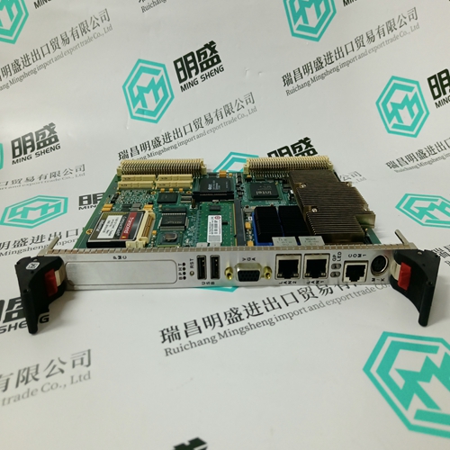
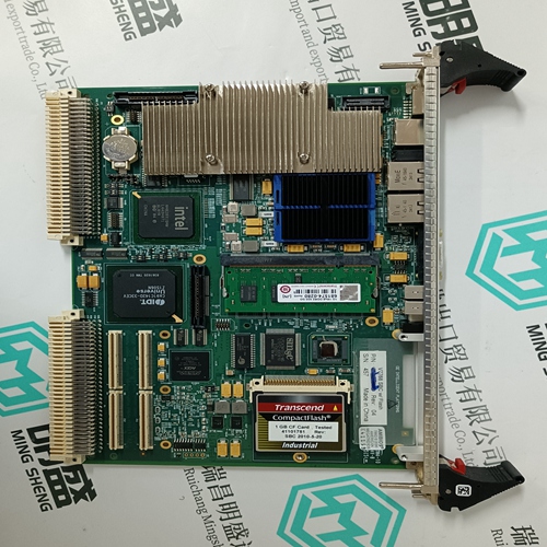
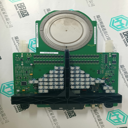
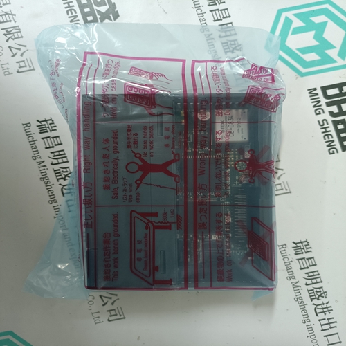
V7768-320001 Combustion engine general card
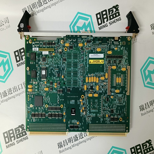
- Product ID: V7768-320001
- Brand: GE
- Place of origin: the United States
- Goods status: new/used
- Delivery date: stock
- The quality assurance period: 365 days
- Phone/WhatsApp/WeChat:+86 15270269218
- Email:stodcdcs@gmail.com
- Tags:V7768-320001Combustion engine general card
- Get the latest price:Click to consult
The main products
Spare parts spare parts, the DCS control system of PLC system and the robot system spare parts,
Brand advantage: Allen Bradley, BentlyNevada, ABB, Emerson Ovation, Honeywell DCS, Rockwell ICS Triplex, FOXBORO, Schneider PLC, GE Fanuc, Motorola, HIMA, TRICONEX, Prosoft etc. Various kinds of imported industrial parts
V7768-320001 Combustion engine general card
3Φ APPARENT POWER DEMAND LEVEL: When the three-phase apparent power demand equals or exceeds this setpoint, a three-phase apparent power alarm or process control indication will occur.PULSE INPUT 1(4) RELAY: Any of the PQMII switch inputs can be assigned to count pulse inputs as shown in 5.3.4 Switch Inputs. This setpoint can be used to give an indication (alarm or control) if the programmed level is equaled or exceeded. Set this setpoint to “Off” if the feature is not required. Selecting “Alarm” activates the alarm relay and displays an alarm message whenever a pulse count level equals or exceeds the selected level. Selecting “Aux1”, “Aux2”, or “Aux3” activates the appropriate auxiliary relay but no message is displayed. The “Aux1”, “Aux2”, and “Aux3” selections are intended for process control. • PULSE INPUT 1(4) LEVEL: When the pulse input value accumulated in the A1 METERING ÖØ PULSE COUNTER ÖØ PULSE INPUT 1(4) actual value equals or exceeds this setpoint value, the relay assigned in the PULSE INPUT 1(4) RELAY will energize. If the “Alarm” relay is assigned, a PULSE INPUT 1(4) ALARM message will also be displayed. The units in this setpoint are determined by the S2 SYSTEM SETUP ÖØ PULSE INPUT ÖØ PULSE INPUT UNITS setpoint.
PULSE INPUT 1(4) DELAY
This setpoint can be used to allow a time delay before the assigned relay will energize after the PULSE INPUT 1(4) LEVEL has been equaled or exceeded. • TOTALIZED PULSES RELAY: A relay can be selected to operate based upon a Total Pulse Input Count as configured in the PQMII. Selecting “Alarm” activates the alarm relay and displays an alarm message whenever a pulse count level equals or exceeds the selected level. Selecting “Aux1”, “Aux2”, or “Aux3” activates the appropriate auxiliary relay but no message will be displayed. The “Aux1”, “Aux2”, and “Aux3” selections are intended for process control. • TOTAL PULSES LEVEL: When the pulse input value accumulated in the A1 METERING ÖØ PULSE COUNTER ÖØ PULSE INPUT 1+2+3+4 actual value exceeds this setpoint value, the relay assigned in the TOTALIZED PULSES RELAY will energize. If the “Alarm” relay is assigned, a TOTALIZED PULSES ALARM message will also be displayed. The units in this setpoint are determined by the S2 SYSTEM SETUP ÖØ PULSE INPUT ÖØ PULSE INPUT UNITS setpoint. • TOTALIZED PULSES DELAY: This setpoint can be used to allow a time delay before the assigned relay will energize after the TOTAL PULSES LEVEL has been equaled or exceeded