Home > Product > Gas turbine system > GE DS200RTBAG1A Gas turbine characteristic module
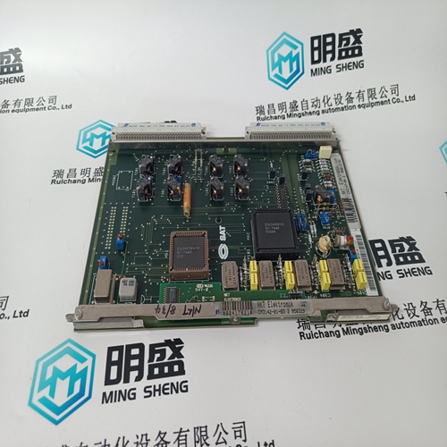
GE DS200RTBAG1A Gas turbine characteristic module
- Product ID: DS200RTBAG1A
- Brand: GE
- Place of origin: The United States
- Goods status: new/used
- Delivery date: stock
- The quality assurance period: 365 days
- Phone/WhatsApp/WeChat:+86 15270269218
- Email:xiamen2018@foxmail.com
- Tags:GEDS200RTBAG1AGas turbine characteristic module
- Get the latest price:Click to consult
GE DS200RTBAG1A Gas turbine characteristic module
This section provides a list of the reference material used in the preparation of this manual.This appendix provides hints and suggestions to aid developers of application I/O hardware targeted for the Twisted Pair Control Modules. The I/O circuit designer is constrained by the programming model and internal hardware of the Neuron Chip. The constraints on I/O pin usage are defined in Reference
The AIB does not buffer the 11-I/O and ~SERVICE pins of the Neuron Chip. The ~SERVICE signal only reaches the interface adapter if the JP4 jumper marked on the AIB is installed. The ~RESET signal on the AIB is a buffered CMOS input to the Neuron Chip on the Emulator. This buffering does not allow direct testing of an I/O circuit using ~RESET as an output from the Neuron Chip
State Transition Timing
The state transition timing for Neuron Chip I/O signals after reset depends on the external memory included in the node implementation. The control modules contain a fixed set of memory resources which do not include external RAM. Therefore, the I/O state transitions during reset are bounded by the slowest input clock frequency, 5MHz. Figure 14 shows typical I/O state transition behavior for a 5 MHz module during reset. The TP/FT-10F, TP/XF-78F, and TP/XF-1250 modules running at 10MHz will take roughly 61ms to achieve the initial I/O pin state after the rising edge of the reset signal.
MAI Considerations
The LonBuilder and NodeBuilder tools include a Model 21860 Module Application Interface (MAI) and cable that can be used in place of a twisted pair control module for testing your target device. The cable connects the MAI to a LonBuilder Application Interface Board or a NodeBuilder LTM-10 Node.The MAI has two jumpers to control the power distribution for the I/O circuit under development. If JP1 is installed, the I/O circuit under development can use up to 400 mA of regulated +5V from the LonBuilder processor board or NodeBuilder LTM-10 Node through the pin P1.12. If JP2 is installed, 35 mA of regulated +12V from the LonBuilder processor board is available through pin P1.1 (+12V is not available on the LTM-10 node). If the power supply circuit for the target device sources the power, JP1 and JP2 must be removed.

Company product range
----------------------Ruichang Mingsheng Automation Equipment Co., Ltd----------------------
PLC module, programmable controller, CPU module, IO module, DO module, AI module, DI module
Network communication module,
Ethernet module, motion control module, analog input module, analog output module, digital input module, digital output
Module, redundancy module, power module, relay output module, relay input module, processor module