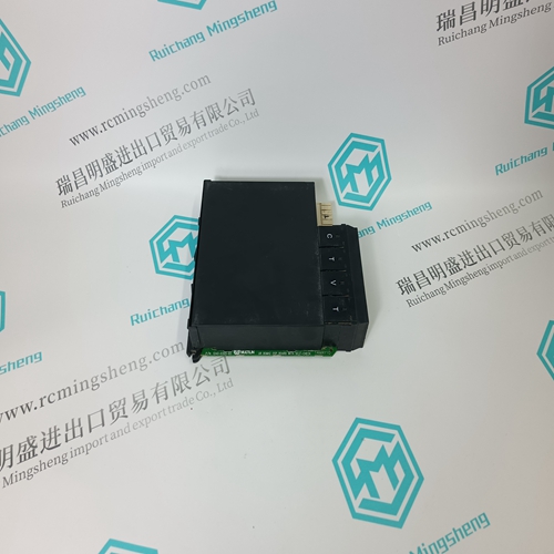
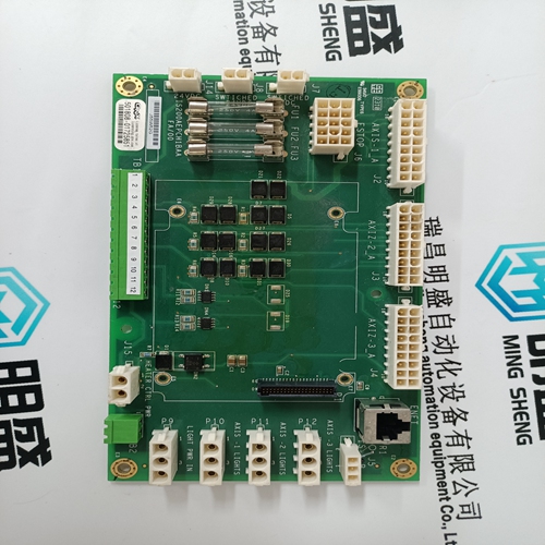
Home > Product > DCS control system > FBM207 P0914TD Channels of contact module
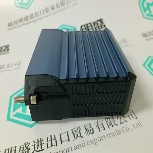
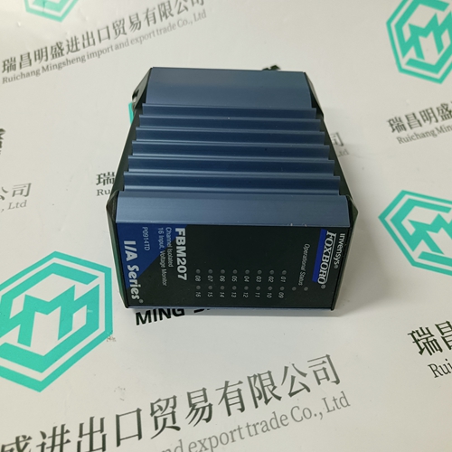
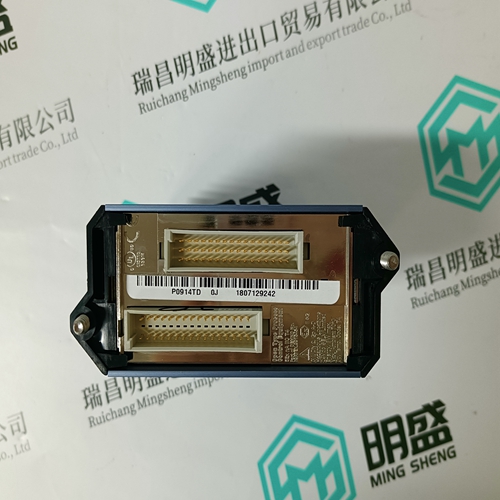
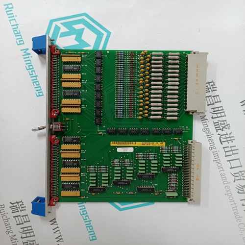
FBM207 P0914TD Channels of contact module
- Product ID: FBM207 P0914TD
- Brand: FOXBORO
- Place of origin: The United States
- Goods status: new/used
- Delivery date: stock
- The quality assurance period: 365 days
- Phone/WhatsApp/WeChat:+86 15270269218
- Email:stodcdcs@gmail.com
- Tags:FBM207 P0914TDChannels of contact module
- Get the latest price:Click to consult
The main products
Spare parts spare parts, the DCS control system of PLC system and the robot system spare parts,
Brand advantage: Allen Bradley, BentlyNevada, ABB, Emerson Ovation, Honeywell DCS, Rockwell ICS Triplex, FOXBORO, Schneider PLC, GE Fanuc, Motorola, HIMA, TRICONEX, Prosoft etc. Various kinds of imported industrial parts
FBM207 P0914TD Channels of contact module
SIMULATION ENABLED FOR: Select the desired length of time to enable simulation. When the programmed time has elapsed, current and voltage simulation will turn off. If “Unlimited” is selected, simulated currents and voltages will be used until simulation is turned off via the SIMULATION setpoint or via the serial port or until control power is removed from the PQMII. • PHASE A/B/C/NEUTRAL CURRENT: Enter the desired phase and neutral currents for simulation. • Vax/Vbx/Vcx VOLTAGE: Enter the desired voltages for simulation. The voltages entered will be line or phase quantities depending upon the VT wiring type selected with the S2 SYSTEM SETUP ÖØ CURRENT/VOLTAGE CONFIGURATION ÖØ VT WIRING setpoint. • PHASE ANGLE: This setpoint represents the phase shift from a unity power factor. Enter the desired phase angle between the current and voltage. The angle between the individual currents and voltages is fixed at 120°.
Simulated currents and voltages can be forced instead of using actual currents or voltages. This allows for verification of current and voltage related functions. • SIMULATION: Enter “On” to switch from actual currents and voltages to the programmed simulated values. Return to “Off” after simulation is complete.
SIMULATION
Enter “On” to switch from actual analog outputs to the programmed simulated values. Set this setpoint “Off” after simulation is complete. • SIMULATION ENABLED FOR: Select the desired length of time that simulation will be enabled. When the programmed time has elapsed, analog output simulation will turn off. If unlimited is selected, simulated analog outputs will be used until simulation is turned off via the SIMULATION setpoint or via the serial port or until control power is removed from the PQMII. • ANALOG OUTPUT 1(4): Enter the percentage of analog output to be simulated. The output is 0 to 1 or 4 to 20 mA, depending upon the installed option. For example, alter the setpoints below: S5 TESTING ÖØ ANALOG OUTPUTS SIMULATION ÖØ ANALOG OUTPUT 1: “50.0%” S5 TESTING ÖØ ANALOG OUTPUTS SIMULATION Ö SIMULATION: “On” The output current level on Analog Output 1 will be 12 mA (4 to 20mA) or 0.5 mA (0 to 1mA).