Home > Product > DCS control system > GDB021BE05 HIEE300766R0005 Control card
GDB021BE05 HIEE300766R0005 Control card
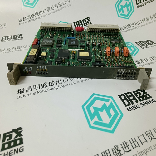
- Product ID: GDB021BE05 HIEE300766R0005
- Brand: ABB
- Place of origin: The Swiss
- Goods status: new/used
- Delivery date: stock
- The quality assurance period: 365 days
- Phone/WhatsApp/WeChat:+86 15270269218
- Email:stodcdcs@gmail.com
- Tags:GDB021BE05 HIEE300766R0005Control card
- Get the latest price:Click to consult
The main products
Spare parts spare parts, the DCS control system of PLC system and the robot system spare parts,
Brand advantage: Allen Bradley, BentlyNevada, ABB, Emerson Ovation, Honeywell DCS, Rockwell ICS Triplex, FOXBORO, Schneider PLC, GE Fanuc, Motorola, HIMA, TRICONEX, Prosoft etc. Various kinds of imported industrial parts
GDB021BE05 HIEE300766R0005 Control card
SIMULATION: Enter “On” to switch from an actual analog input to the programmed simulated value. Set this setpoint “Off” after simulation is complete. • SIMULATION ENABLED FOR: Select the desired length of time to run simulation. When the programmed time has elapsed, analog input simulation will end. If “Unlimited” is selected, the simulated analog input will be used until simulation is turned off via the SIMULATION setpoint or via the serial port or until control power is removed from the PQMII. • ANALOG INPUT: Enter an analog input current in the range of 4 to 20 mA to be simulated. SIMULATION: Enter “On” to switch from actual switch inputs to the programmed simulated switches. Set this setpoint “Off” after simulation is complete. • SIMULATION ENABLED FOR: Select the desired length of time that simulation will be enabled. When the programmed time has elapsed, switch input simulation will turn off. If “Unlimited” is selected, the simulated switch inputs will be used until simulation is turned off via the SIMULATION setpoint or via the serial port or until control power is removed from the PQMII. • SWITCH INPUT A(D): Enter the switch input status (open or closed) to be simulated.
Actual Values Viewing
Any measured value can be displayed on demand using the MENU and MESSAGE keys. Press the MENU key to select the actual values, then the MESSAGE RIGHT key to select the beginning of a new page of monitored values. These are grouped as follows: A1 Metering, A2 Status, A3 Power Analysis, and A4 Product Info. Use the MESSAGE keys to move between actual value messages. A detailed description of each displayed message in these groups is given in the sections that follow.
A, B, C CURRENT: Displays the current in each phase corresponding to the A, B, and C phase inputs. Current will be measured correctly only if the CT PRIMARY is entered to match the installed CT primary and the CT secondary is wired to match the 1 or 5 A input. If the displayed current does not match the actual current, check this setpoint and wiring. • Iavg/Vavg: Displays the average of the three phase currents and three voltages. This line is not visible if the VT WIRING setpoint is set to “Single Phase Direct”. L-N is displayed when VT WIRING is set to “4 Wire Wye /3 VTs”, “4 Wire Wye Direct”, “4 Wire Wye / 2 VTs”, or “3 Wire Direct”. L-L is displayed when VT WIRING is set to “3 Wire Delta / 2 VTs”.