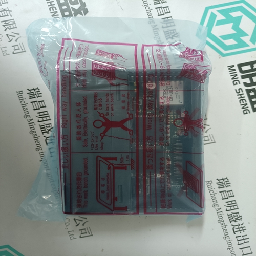
Home > Product > DCS control system > TU847 3BSE022462R1 base module
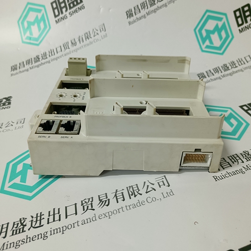
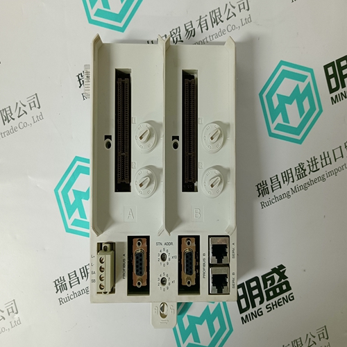
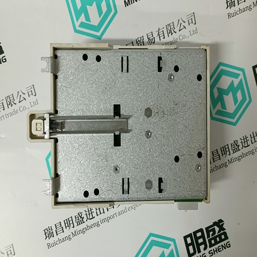
TU847 3BSE022462R1 base module
- Product ID: TU847 3BSE022462R1
- Brand: ABB
- Place of origin: The Swiss
- Goods status: new/used
- Delivery date: stock
- The quality assurance period: 365 days
- Phone/WhatsApp/WeChat:+86 15270269218
- Email:stodcdcs@gmail.com
- Tags:TU847 3BSE022462R1base module
- Get the latest price:Click to consult
The main products
Spare parts spare parts, the DCS control system of PLC system and the robot system spare parts,
Brand advantage: Allen Bradley, BentlyNevada, ABB, Emerson Ovation, Honeywell DCS, Rockwell ICS Triplex, FOXBORO, Schneider PLC, GE Fanuc, Motorola, HIMA, TRICONEX, Prosoft etc. Various kinds of imported industrial parts
TU847 3BSE022462R1 base module
NEUTRAL CURRENT: Neutral current can be determined by two methods. One method measures the current via the neutral CT input. The second calculates the neutral current based on the three phase currents; using the instantaneous samples, I a + I b + I c = I n. If the sum of the phase currents does not equal 0, the result is the neutral current. When using the CT input, the neutral current reading will be correct only if the CT is wired correctly and the correct neutral CT primary value is entered. Verify neutral current by connecting a clamp-on ammeter around all 3 phases. If the neutral current appears incorrect, check the settings in S2 SYSTEM SETUP ÖØ CURRENT/VOLTAGE CONFIGURATION and verify the CT wiring.
Even though it is possible to achieve unbalance greater than 100% with the above formula, the PQMII limits unbalance readings to 100%. If the average current is below 10% of the CT PRIMARY setpoint, the unbalance reading is forced to 0%. This avoids nuisance alarms when the system is lightly loaded. If the simulation currents are being used, the unbalance is never forced to 0%. • Ia, Ib, Ic, In MIN: Displays the minimum current magnitudes and the time and date of their occurrence. This information is stored in non-volatile memory and is retained during loss of control power. The S1 PQMII SETUP ÖØ CLEAR DATA ÖØ CLEAR MIN/MAX CURRENT VALUES setpoint clears these values.
VOLTAGE UNBALANCE
Displays the percentage voltage unbalance. Voltage unbalance is calculated as shown below. If the VOLTAGE WIRING is configured for a wye input, voltage unbalance is calculated using phase quantities. If the VT WIRING is configured as a delta input, voltage unbalance is calculated using line voltages.
I U/B MIN: Displays the minimum current unbalance and the time and date of its measurement. This information is stored in non-volatile memory and is retained during loss of control power. The S1 PQMII SETUP ÖØ CLEAR DATA ÖØ CLEAR MIN/MAX CURRENT VALUES setpoint clears this value. • Ia, Ib, Ic, In MAX: Displays the maximum current magnitudes and the time and date of their occurrence. This information is stored in non-volatile memory and is retained during loss of control power. The S1 PQMII SETUP ÖØ CLEAR DATA ÖØ CLEAR MIN/MAX CURRENT VALUES setpoint clears these values. • I U/B MAX: Displays the maximum current unbalance and the time and date of its measurement. This information is stored in non-volatile memory and is retained during loss of control power. The S1 PQMII SETUP ÖØ CLEAR DATA ÖØ CLEAR MIN/MAX CURRENT VALUES setpoint command clears this value.
