Home > Product > Gas turbine system > GE DS200CFBG1BLC Valve position controller
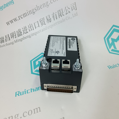
GE DS200CFBG1BLC Valve position controller
- Product ID: DS200CFBG1BLC
- Brand: GE
- Place of origin: The United States
- Goods status: new/used
- Delivery date: stock
- The quality assurance period: 365 days
- Phone/WhatsApp/WeChat:+86 15270269218
- Email:xiamen2018@foxmail.com
- Tags:GEDS200CFBG1BLCValve position controller
- Get the latest price:Click to consult
GE DS200CFBG1BLC Valve position controller
Here is only the direct connection between motor and drive controller described. The connection diagrams are also guilty for all other connections (e.g. with intermediate connection). There is no change with coordinating the motor and drive controller connections.MKD motors can be supplied optionally with axial or radial blower. The various connection possibilities are described in the table below. Please refer to the technical data for the fan units available.
To establish the connection, the fan plug must be opened and closed. • The electric connection may be established by qualified technical personnel only. Please observe the safety instructions. • The housing tightness may not be reduced.
Connecting and mounting the blower
A three-core cable with a connection cross-section of at least 0.75 mm2 must be used as connection cable.
Proceed as follows to mount the connection cable to the fan plug:
1. Loosen the heavy-gauge conduit thread (6) (size 17).
2. Turn the cylinder screw (1) out of the socket (4) using the screwdriver (5).
3. Pull off the plug housing (2) including the plug insert (3) from the flange socket (4).
4. Pull out the cylinder screw
5. Remove the plug insert (3) from the plug housing
Dimensioning of power cable
The specified and calculated cross sectional area of the cables in this Rexroth Indramat documentation base on RMS current and the assumption for “rotating motors”. Base for this calculation are the specified stillstand-constant current in the technical data. They are specified as peak values. The relevant electric currents are in association as follows:Generally is the dimensioning after RMS current at a “rotating motor” sufficient.In some cases, applications, working over a longer period, require a continuous torque at standstill when speed = 0 min 1 for the motors (standard value see Fig. 12.14) is recommended to manage the cabledimensioning as specified peak values in the technical datas (“standstill motor”).

Common problem
We have this product in stock, and we can deliver it to you at any time when you need it badly.
*The warranty period of all products is 1 year, which has passed the professional test certification.
*If you need to order more than one product, please contact us, and we can offer you a discount.
*We only use HDL UPS and other express delivery methods to deliver spare parts.
*If you find that other suppliers offer lower prices for the same products, we are also willing to offer you further discounts based on their prices.
If you have any other questions, please feel free to contact us via email.
*Please let us know if you need any spare parts, we can give you further assistance, and we are waiting for your inquiry.