Home > Product > Gas turbine system > GE IS200EDCFG1AED DC input module
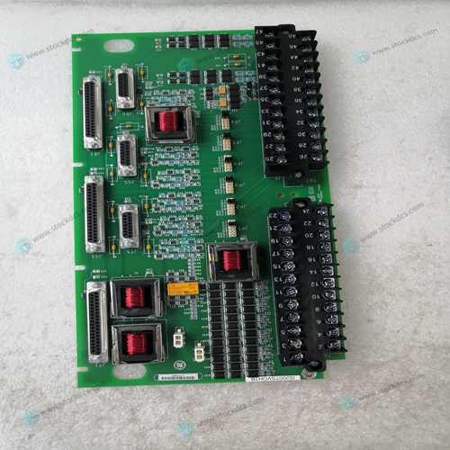
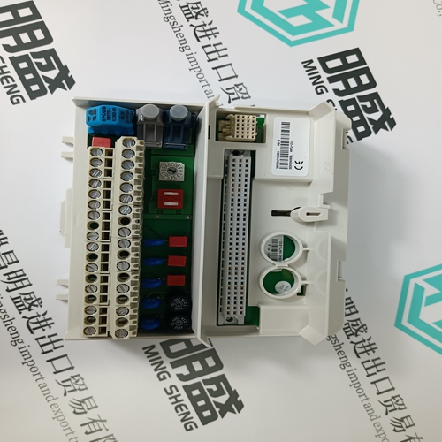
GE IS200EDCFG1AED DC input module
- Product ID: IS200EDCFG1AED
- Brand: GE
- Place of origin: The United States
- Goods status: new/used
- Delivery date: stock
- The quality assurance period: 365 days
- Phone/WhatsApp/WeChat:+86 15270269218
- Email:stodcdcs@gmail.com
- Tags:GEIS200EDCFG1AEDDC input module
- Get the latest price:Click to consult
GE IS200EDCFG1AED DC input module
Example Application Program 1 In voltage input mode, the 2AD converts analog values from 0 ~ 10V to the digital output of 0 ~ 4000. If using a digital range of 0 ~ 10000 in the program, the range must be converted from 0 ~ 4000 to 0 ~ 10000 as shown in the programming example below. Digital values that are converted from analog values are stored in D8112 or D8113. The analog input does not have exact resolution of 2.5 mV because the digital value is converted from a range of 0 ~ 4000 to 0 ~ 10000.If a digital value in the range of 0 ~ 10000 is used in D10, please see below. Digital value used in user program: D10 = 10 × (D8112 or D8113) ÷ 4 The program example based on the equation above is as shown in the figure below
Example Application Program 2
In current input mode, the 2AD converts analog values from 4 ~ 20mA to the digital output of 0 ~ 2000. If using a digital range of 4000 ~ 20000 in the program, the range must be converted from 0 ~ 2000 to 4000 ~ 20000 as shown in the programming example below. Digital values that are converted from analog values are stored in D8112 or D8113. The analog input does not have exact resolution of 8 μA because the digital value is converted from a range of 0 ~ 2000 to 4000 ~ 20000.If a digital value in the range of 4000 ~ 20000 is used in D60, please see below. Digital value used in user program: D60 = 8 × (D8112 or D8113) + 4000 The program example based on the equation above is as shown in the figure below.
Basic Example Program
Note: • Drive M8112 and M8113 which specifies the analog to digital conversion characteristic with M8000 (“a” type contact of the RUN monitor) or M8001 (“b” type contact of the RUN monitor). Do not change the ON/OFF state while the analog to digital conversion is operating. The analog to digital conversion is not executed correctly when M8112 or M8113 are turned ON and OFF during the conversion process. • Do not change the digital value of D8112 or D8113 after A/D conversion in the 2AD, by manipulating the user program, a programming tool, or GOT (graphic operation terminal), etc. The following program example sets Ch1 in the voltage input mode, Ch2 in the current input mode, with the A/D converted digital value of each channel stored in D0 and D1.


Common problem
We have this product in stock, and we can deliver it to you at any time when you need it badly.
*The warranty period of all products is 1 year, which has passed the professional test certification.
*If you need to order more than one product, please contact us, and we can offer you a discount.
*We only use HDL UPS and other express delivery methods to deliver spare parts.
*If you find that other suppliers offer lower prices for the same products, we are also willing to offer you further discounts based on their prices.
If you have any other questions, please feel free to contact us via email.
*Please let us know if you need any spare parts, we can give you further assistance, and we are waiting for your inquiry.
