Home > Product > Gas turbine system > PCH1026 Channel touch point card
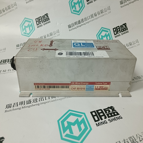
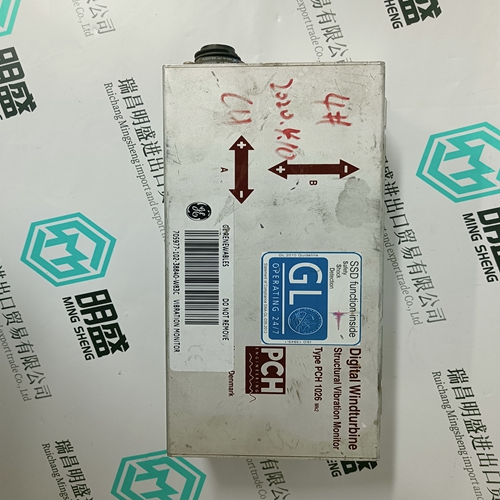
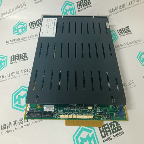
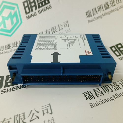
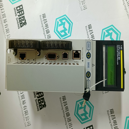
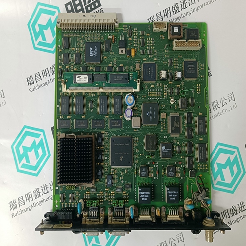
PCH1026 Channel touch point card
- Product ID: PCH1026
- Brand: GE
- Place of origin: the United States
- Goods status: new/used
- Delivery date: stock
- The quality assurance period: 365 days
- Phone/WhatsApp/WeChat:+86 15270269218
- Email:stodcdcs@gmail.com
- Tags:PCH1026Channel touch point card
- Get the latest price:Click to consult
The main products
Spare parts spare parts, the DCS control system of PLC system and the robot system spare parts,
Brand advantage: Allen Bradley, BentlyNevada, ABB, Emerson Ovation, Honeywell DCS, Rockwell ICS Triplex, FOXBORO, Schneider PLC, GE Fanuc, Motorola, HIMA, TRICONEX, Prosoft etc. Various kinds of imported industrial parts
PCH1026 Channel touch point card
To assist in troubleshooting, the state of each switch can be verified using these messages. A separate message displays the status of each input identified by the corresponding name as shown in the wiring diagrams in chapter 2. For a dry contact closure across the corresponding switch terminals the message will read “Closed”.The current time and date is displayed in this message. The PQMII uses an internally generated software clock which runs for approximately thirty days after the control power has been removed. For instructions on setting the clock, see 5.2.6 Clock. The S4 ALARMS/ CONTROL ÖØ MISCELLANEOUS ÖØ CLOCK NOT SET ALARM alarm occurs if power has been removed for longer than thirty days and the clock value has been lost.
A 40-character user defined message is displayed. The message is programmed using the keypad or via the serial port using the EnerVista PQMII Setup Software. See 6.3.4 Programmable Message for programming details Ia/Ib/Ic CREST FACTOR: The crest factor describes how much the load current can vary from a pure sine wave while maintaining the system’s full rating. A completely linear load (pure sine wave) has a crest factor of (1 /0.707), which is the ratio of the peak value of sine wave to its RMS value. Typically, the crest factor can range from to 2.5.