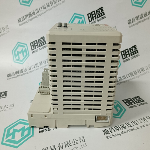
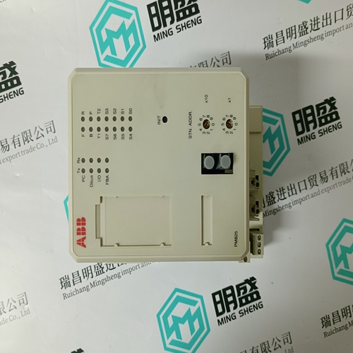
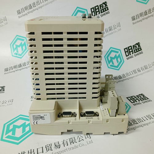
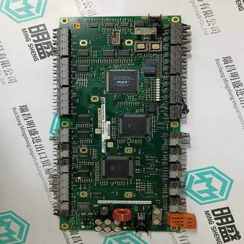
Home > Product > DCS control system > PM825 3BSE010796R1 Sequence controller
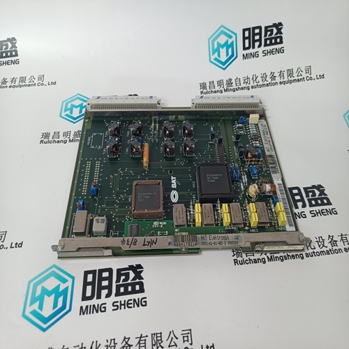
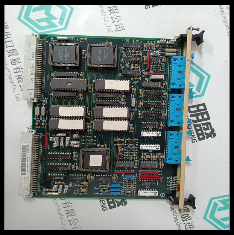
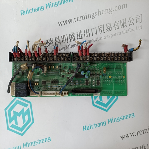
PM825 3BSE010796R1 Sequence controller
- Product ID: PM825 3BSE010796R1
- Brand: ABB
- Place of origin: The Swiss
- Goods status: new/used
- Delivery date: stock
- The quality assurance period: 365 days
- Phone/WhatsApp/WeChat:+86 15270269218
- Email:stodcdcs@gmail.com
- Tags:PM825 3BSE010796R1Sequence controller
- Get the latest price:Click to consult
The main products
Spare parts spare parts, the DCS control system of PLC system and the robot system spare parts,
Brand advantage: Allen Bradley, BentlyNevada, ABB, Emerson Ovation, Honeywell DCS, Rockwell ICS Triplex, FOXBORO, Schneider PLC, GE Fanuc, Motorola, HIMA, TRICONEX, Prosoft etc. Various kinds of imported industrial parts
PM825 3BSE010796R1 Sequence controller
Van/Vbn/Vcn/Vab/Vbc MAX THD: These messages display the maximum total harmonic value for each voltage input and the time and date of its occurrence. The setpoint S1 PQMII SETUP ÖØ CLEAR DATA \ÖØCLEAR MAX THD VALUES is used to clear this value. Phase to neutral voltages will appear when the setpoint S2 SYSTEM SETUP ÖØ CURRENT/ VOLTAGE CONFIGURATION ÖØ VT WIRING is set to “Wye”. Line to line voltages will appear when VT WIRING is set to “Delta”.
be set up and run only from the EnerVista PQMII Setup Software. See 4.5.4 Data Logger and 8.6 Data Logger Implementation for additional details on the Data Logger feature. It is possible to stop the data loggers from the PQMII front panel using the S2 SYSTEM SETUP ÖØ DATA LOGGER ÖØ STOP DATA LOGGER 1(2) setpoint.The event data stored for POWER OFF events does not reflect values at the time of power-off. These messages display the 150 most recent events recorded by the event recorder. The list of possible events and their display on the PQMII is shown below.
Event Recorder
The PQMII Event Recorder runs continuously and records the number, cause, time, date, and metering quantities present at the occurrence of each event. This data is stored in non-volatile memory and is not lost when power to the PQMII is removed. The Event Recorder must be enabled in S1 PQMII SETUP ÖØ EVENT RECORDER ÖØ EVENT RECORDER OPERATION. The Event Recorder can be cleared in S1 PQMII SETUP ÖØ CLEAR DATA ÖØ CLEAR EVENT RECORD. Data for the 150 most recent events is stored. Event data for older events is lost. Note that the event number, cause, time, and date is available in the messages as shown in the following table, but the associated metering data is available only via serial communications.The Voltage Disturbance Recorder runs continuously and records the source, level and duration of each voltage disturbance. Up to 500 disturbances are recorded in a circular buffer. When over 500 disturbances are recorded, data for older disturbances are lost as new disturbances are recorded. Additionally, since the events are stored within volatile memory, the voltage disturbance recorder will lose all events upon a power loss. The time and date of when the disturbance ended is recorded with the disturbance event. The following available is available for each disturbance: • Type: Each disturbance is classified as a SWELL or SAG. The disturbance will be distinguished as a swell if the voltage increases above the swell level, for up to 1 minute. A sag disturbance is distinguished in the same manner except that it involves a voltage decrease below the sag level. • Source: The source of the disturbance is the phase voltage that recorded the disturbance; either Van, Vbn, Vcn, Vab, or Vca. If the disturbance is found on two or more phases, multiple disturbances will be recorded.
