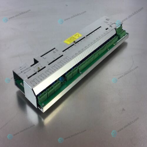
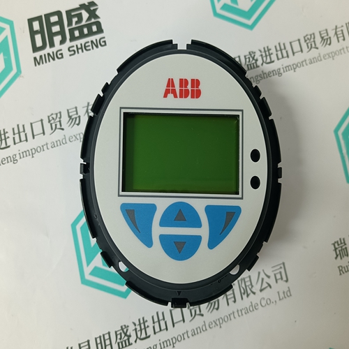
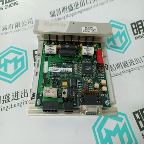
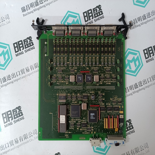
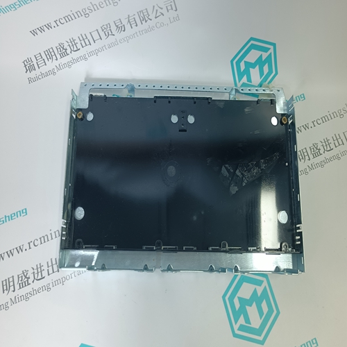
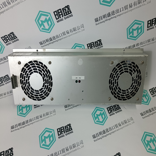
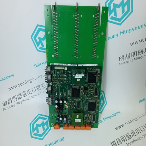
Home > Product > DCS control system > ABB UA C383 AE01 HIEE300890R0001 Pulse interface module
ABB UA C383 AE01 HIEE300890R0001 Pulse interface module
- Product ID: UA C383 AE01 HIEE300890R0001
- Brand: ABB
- Place of origin: The Swiss
- Goods status: new/used
- Delivery date: stock
- The quality assurance period: 365 days
- Phone/WhatsApp/WeChat:+86 15270269218
- Email:stodcdcs@gmail.com
- Tags:ABBUA C383 AE01HIEE300890R0001Pulse interface module
- Get the latest price:Click to consult
ABB UA C383 AE01 HIEE300890R0001 Pulse interface module
The topologies shown in the previous diagrams do not show the Signal Ground for reasons of clarity. On all the above circuits, Signal Ground must be connected for correct operation. It is also important not to connect the signal ground to the chassis ground. The Signal Grounds for each port on the CI should be kept separate from each other to maintain the isolation between ports. It is recommended that when specifying cables that an extra twisted pair is specified to carry the signal ground connection. Signal ground should not be connected to the cable screen because the cable screen should be used for EMI shielding and should be connected to chassis ground
A and B Circuit Designators
The ‘A’ and ‘B’ circuit designators are often a source of confusion for systems integrators. This is not helped by the use of non-standard ‘+’ and ‘-’ symbols on some equipment. To determine which terminal is ‘A’ and which is ‘B’, set the line to the ‘Idle’ or ‘Off’ state. Connect a multimeter on the volts range across the ‘A’ and ‘B’ terminals. When the multimeter reads a negative voltage, the +ve terminal of the multimeter is connected to ‘A’ and the -ve terminal is connected to ‘B’. The ‘+’ and ‘-’ symbols shown on some equipment are rarely very reliable at indicating which circuit is which unless connecting equipment of the same make together. There is no standard for matching ‘+’ and ‘-’ to ‘A’ and ‘B’. It is therefore important to refer to the manufacturer’s handbook or to test the line as in the previous paragraph
Maximum Cable Length
The maximum length of an RS485 system is dependent on cable type, data rate and termination. For example, the EIA RS-422-A standard gives a maximum length of 4000 ft (approx. 1.2 Km) for 24AWG twisted pair telephone cable that has a shunt capacitance of 16 pF/ft, a 100 Ω termination and a data rate of 100 kbits/s. 6.2.7. RS485 Connections The pin-outs and signal labels for the CI RS485 ports are shown in Table 22 below. Further details are given in PD-T8153. The maximum number of nodes that the CI supports before hardware build C for multi-drop applications is 6. From hardware build C, the module has internal terminations changed to support the full 32 drop capacity.


Our superior products
ABB -- AC 800M controller, Bailey, PM866 controller, IGCT silicon controlled 5SHY 3BHB01 3BHEO0 3HNA00 DSOC series
BENTLY --- 3500 system/proximitor, front and rear cards, sensors, power modules, probes, cables
Emerson -- modbus card, power panel, controller, power supply, base, power module, switch
EPRO --- Data acquisition module, probe, speed sensor, vibration sensor, shaft vibration transmitter, proximitor
FOXBORO - thermal resistance input/output module, power module, communication module, cable, controller, switch
GE --- module, air switch, I/O module, display, CPU module, power module, converter, CPU board, Ethernet module, integrated protection device, power module, gas turbine card
HIMA --- DI module, processor module, AI card, pulse encoder
Honeywell --- Secure digital output card, program module, analog input card, CPU module, FIM card
MOOG - servo valve, controller, module, power module
NI --- Information acquisition card, PXI module, card, chassis multi-channel control card
WESTINGHOUSE --- RTD thermal resistance input module, AI/AO/DI/DO module, power module, control module, base module
Woodward - Regulator, module, controller, governor
YOKOGAWA - Servo module, control cabinet node unit
