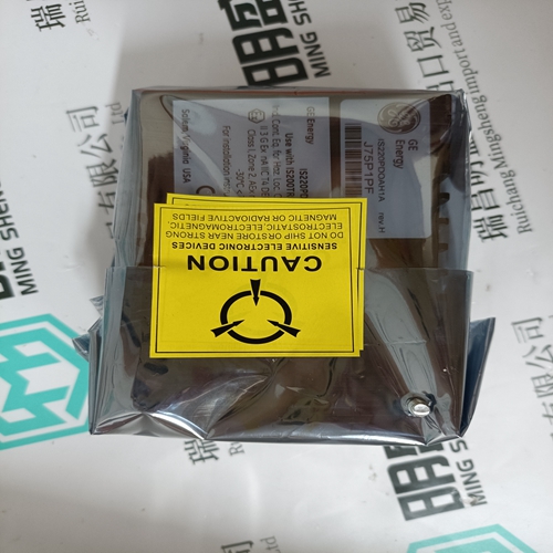
Home > Product > DCS control system > DSAI133A 3BSE018290R1 Output expansion card
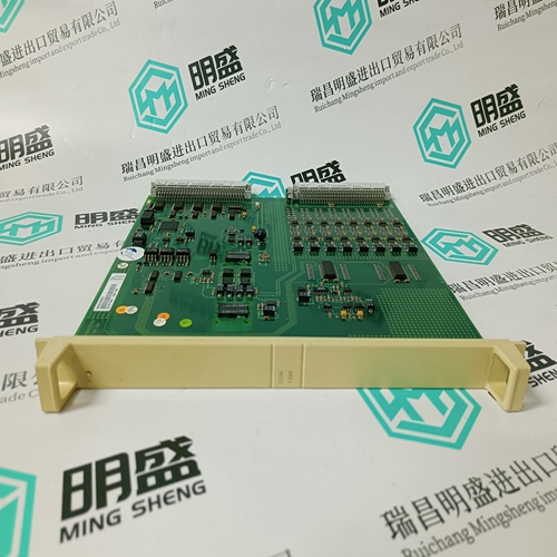
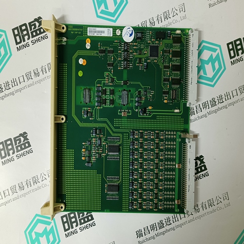
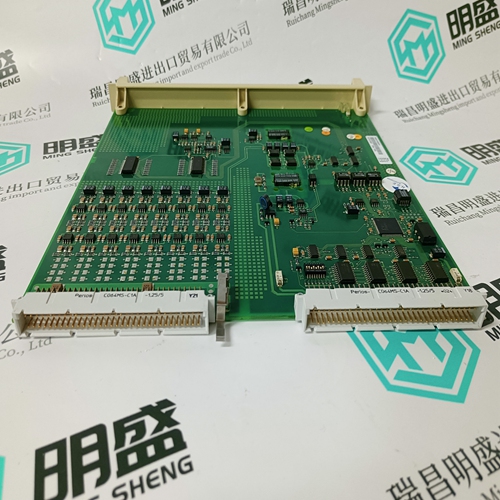
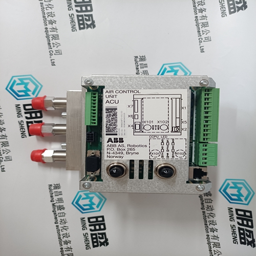
DSAI133A 3BSE018290R1 Output expansion card
- Product ID: DSAI133A 3BSE018290R1
- Brand: ABB
- Place of origin: The Swiss
- Goods status: new/used
- Delivery date: stock
- The quality assurance period: 365 days
- Phone/WhatsApp/WeChat:+86 15270269218
- Email:stodcdcs@gmail.com
- Tags:DSAI133A 3BSE018290R1Output expansion card
- Get the latest price:Click to consult
The main products
Spare parts spare parts, the DCS control system of PLC system and the robot system spare parts,
Brand advantage: Allen Bradley, BentlyNevada, ABB, Emerson Ovation, Honeywell DCS, Rockwell ICS Triplex, FOXBORO, Schneider PLC, GE Fanuc, Motorola, HIMA, TRICONEX, Prosoft etc. Various kinds of imported industrial parts
DSAI133A 3BSE018290R1 Output expansion card
The following table specifies the default variation for all objects returned by the relay. These are the variations that will be returned for the object in a response when no specific variation is specified in a request.The following restrictions should be observed when using object 12 to control the points listed in the following table. 1. The Count field is checked first. If it is zero, the command will be accepted but no action will be taken. If this field is non-zero, the command will be executed exactly once regardless of its value. 2. The Control Code field of object 12 is then inspected: • A NUL Code will cause the command to be accepted without any action being taken. • A Code of “Pulse On” (1) is valid for all points. This is used to activate the function (e.g., Reset) associated with the point. • All other Codes are invalid and will be rejected. • The Queue, Clear, and Trip/Close sub-fields are ignored. 3. The On Time and Off Time fields are ignored. A “Pulse On” Code takes effect immediately when received. Thus, the timing is irrelevant. 4. The Status field in the response will reflect the success or failure of the control attempt thus: • A Status of “Request Accepted” (0) will be returned if the command was accepted. • A Status of “Request not Accepted due to Formatting Errors” (3) will be returned if the Control Code field was incorrectly formatted or an invalid Code was present in the command. • A Status of “Control Operation not Supported for this Point” (4) will be returned in response to a “Latch On” or “Latch Off” command
Analog Input/Output Change
In the following point list for Analog Input/Output Change, the entry in the “Format” column indicates that the format of the associated data point can be determined by looking up the entry in Table 7–2: Data Formats. For example, an “F1” format is described in that table as a (16-bit) unsigned value without any decimal places. Therefore, the value read should be interpreted in this manner.
An operate of the Reset, alarm relay on/off or Aux Relay 1-3 on/off points may fail (even if the command is accepted) due to other inputs or conditions (e.g., alarm conditions) existing at the time. To verify the success or failure of an operate of these points it is necessary that the associated Binary Input(s) be examined after the control attempt is performed. 6. When using object 10 to read the status of a Binary Output, a read will always return zero.
However, this Event Number is usually not known and the entire Event Record must be read. The easiest way to do this is to read the PQMII Memory Map location 0AD0h (Total Number of Events Since Last Clear) and loop through each Event Number indicated by the value from 0AD0h, reading the associated data pertaining to each Event. This requires 1 to 150 serial reads of 170 bytes each. Once this data is obtained, it can be interpreted based upon the format of each value as described in 7.3: Modbus Memory Map. It is important to note that some memory map parameters are 32 bits (4 bytes) long and require 2 registers to contain their value, one for the two high bytes and one for the two low bytes.
