Home > Product > DCS control system > ABB 21660559-H DSRA 110 Output expansion card
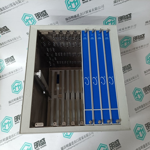
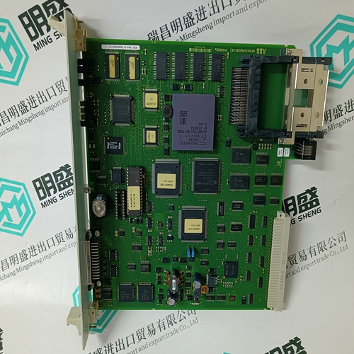
ABB 21660559-H DSRA 110 Output expansion card
- Product ID: 21660559-H DSRA 110
- Brand: ABB
- Place of origin: The Swiss
- Goods status: new/used
- Delivery date: stock
- The quality assurance period: 365 days
- Phone/WhatsApp/WeChat:+86 15270269218
- Email:stodcdcs@gmail.com
- Tags:ABB21660559-HDSRA 110Output expansion card
- Get the latest price:Click to consult
ABB 21660559-H DSRA 110 Output expansion card
This bi-directional transference of data is accomplished by the module filling in data in the module's input image to send to the processor. Data in the input image is placed in the Controller Tags in the processor by the ladder logic. The input image for the module is set to 250 words. This large data area permits fast throughput of data between the module and the processor. The processor inserts data into the module's output image to transfer to the module. The module's program extracts the data and places it in the module's internal database. The output image for the module is set to 248 words. This large data area permits fast throughput of data from the processor to the module The following illustration shows the data transfer method used to move data between the ControlLogix processor and the MVI56-EGD module.
All data transferred between the module
the processor over the backplane is through the input and output images. Ladder logic must be written in the ControlLogix processor to interface the input and output image data with data defined in the Controller Tags. All data used by the module is stored in its internal database. The following illustration shows the layout of the database Data contained in this database is paged through the input and output images by coordination of the ControlLogix ladder logic and the MVI56-EGD module's program. Up to 248 words of data can be transferred from the module to the processor at a time. Up to 247 words of data can be transferred from the processor to the module. The read and write block identification codes in each data block determine the function to be performed or the content of the data block.
Normal Data Transfer
Normal data transfer includes the paging of the user data found in the module’s internal database in registers 0 to 3999 and the status data. These data are transferred through read (input image) and write (output image) blocks. Refer to the Module Configuration and Ladder Logic sections for a description of the data objects used with the blocks and the ladder logic required. The structure and function of each block is discussed in the following topics. Block Request from the Processor to the Module These blocks of data transfer information from the ControlLogix processor to the module and source the input (monitored) data to be used by the remote master. The following table describes the structure of the output image.


Quality assurance service
1. We provide high-quality parts of various brands, and you will find full
The model meets your needs.
2. For models that have been out of production for many years, we have all hard to find parts, so we can directly find us to solve all problems for you at one time.
3. If you are in a hurry to use this product, we can dispatch it for you.
4. All products can enjoy a one-year warranty service,
5. Our products are new and unused.
6. If you need a large quantity, you can contact us and I can offer you a discount.
7. You can ask me about the price and more information about the product via email. We welcome you
