Home > Product > DCS control system > ABB CTT02 Operating the controller
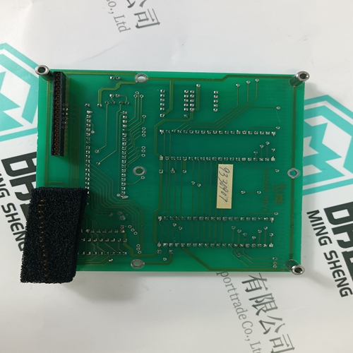
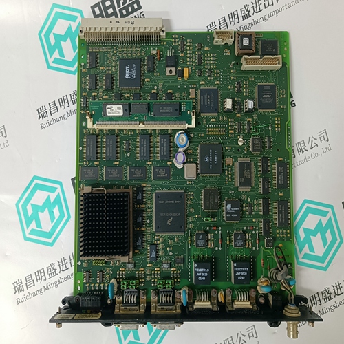
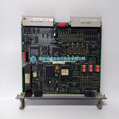
ABB CTT02 Operating the controller
- Product ID: CTT02
- Brand: ABB
- Place of origin: The Swiss
- Goods status: new/used
- Delivery date: stock
- The quality assurance period: 365 days
- Phone/WhatsApp/WeChat:+86 15270269218
- Email:stodcdcs@gmail.com
- Tags:ABBCTT02Operating the controller
- Get the latest price:Click to consult
ABB CTT02 Operating the controller
This port is physically an RJ45 connection. An RJ45 to DB-9 adapter cable is included with the module. This port permits a PC based terminal emulation program to view configuration and status data in the module and to control the module. The cable for communications on this port is shown in the following diagram:When the RS-232 interface is selected, the use of hardware handshaking (control and monitoring of modem signal lines) is user definable. If no hardware handshaking will be used, here are the cable pinouts to connect to the port.This type of connection is required between the module and a modem or other communication device.The "Use CTS Line" parameter for the port configuration should be set to 'Y' for most modem applications. RS-232: Null Modem Connection (Hardware Handshaking) This type of connection is used when the device connected to the module requires hardware handshaking (control and monitoring of modem signal lines).
RS-232: Null Modem Connection (No Hardware Handshaking)
This type of connection can be used to connect the module to a computer or field device communication port. Note: For most null modem connections where hardware handshaking is not required, the Use CTS Line parameter should be set to N and no jumper will be required between Pins 7 (RTS) and 8 (CTS) on the connector. If the port is configured with the Use CTS Line set to Y, then a jumper is required between the RTS and the CTS lines on the port connection.The RS-422 interface requires a single four or five wire cable. The Common connection is optional, depending on the RS-422 network devices used.
RS-485 Application Port(s)
The RS-485 interface requires a single two or three wire cable. The Common connection is optional, depending on the RS-485 network devices used. The cable required for this interface is shown below: Note: Terminating resistors are generally not required on the RS-485 network, unless you are experiencing communication problems that can be attributed to signal echoes or reflections. In these cases, installing a 120-ohm terminating resistor between pins 1 and 8 on the module connector end of the RS-485 line may improve communication quality. RS-485 and RS-422 Tip If communication in the RS-422 or RS-485 mode does not work at first, despite all attempts, try switching termination polarities. Some manufacturers interpret + and -, or A and B, polarities differently.


Brand display
ABB、GE/FUANC、FOXBORO、TRICONEX 、BENTLY、A-B、EMERSON 、MOTOROLA、XYVOM、HONEYWELL 、REXROTH、KUKA、NI、DEIF、Yokogawa、WOODWARD、Reliance Electric、SCHNEIDER 、MOOG、PROSOFT、KOLLMORGEN、ICS TRIPLEX、HIMA。
