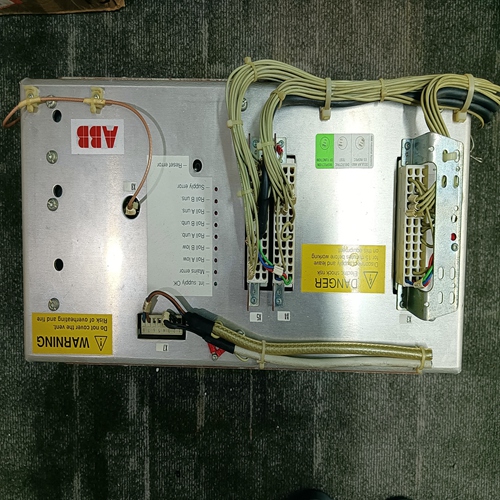
Home > Product > Servo control system > WOODWARD 8440-1713 D Control the governor
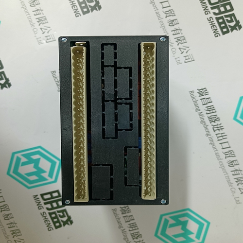
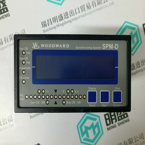
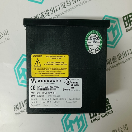
WOODWARD 8440-1713 D Control the governor
- Product ID: 8440-1713 D
- Brand: WOODWARD
- Place of origin: the United States
- Goods status: new/used
- Delivery date: stock
- The quality assurance period: 365 days
- Phone/WhatsApp/WeChat:+86 15270269218
- Email:stodcdcs@gmail.com
- Tags:WOODWARD8440-1713 DControl the governor
- Get the latest price:Click to consult
The main products
Spare parts spare parts, the DCS control system of PLC system and the robot system spare parts,
Brand advantage: Allen Bradley, BentlyNevada, ABB, Emerson Ovation, Honeywell DCS, Rockwell ICS Triplex, FOXBORO, Schneider PLC, GE Fanuc, Motorola, HIMA, TRICONEX, Prosoft etc. Various kinds of imported industrial parts
WOODWARD 8440-1713 D Control the governor
It must be guaranteed that the control voltage is maintained and remains on when power is shut off or in an emergency-off situation. This makes it possible for any occurring faults and intereferences stored in the equipment to be afterwards read-off from the diagnostic display. Only the master switch can completely shut down power to the machine.Switch off master switch. 9. Re-secure mains fuses, or reconnect the power lines between the drive equipment and the mains. Clamp off the connecting wire for controller enable at terminal RF, just to be safe. As soon as the link circuit has reloaded itself via the mains contact to minimum level, and if no fault is present, then the following green diagnostic lamps must remain lit-up: On the supply module: • „power-on“ On the servo-drive module: • „power“ or „PWR“, and, • „Bb“ • the ready-to-operate contact „Bb“ of the servo-drive module closes. The drive is now ready to operate. There are high voltages at the link circuit busbars, mains and motor power connections. It is, therefore, necessary, before accessing hot parts, to disconnect the equipment from the mains, just to be safe, and await the discharge time. Using a multitester, check the link circuit voltage between connecting bolt L+ and L-. The values should range from 255 to 360 volts. Maximum values approximately equal: – 325 volts for mains nominal voltage, and, – 360 volts for mains overvoltage, if the drives have been shut down
Should link circuit voltage be too high
then a wrong transformer or an improper connection could be the reason. If it is too high, then this could be caused by a missing phase, an improper transformer or an incorrect connection on the transformer.
Before activating the drive, make sure that sufficient accident preventive measures have been taken, in accordance with Chap. 6.1. In addition, measures must be taken to avoid damage to the machine which could result from a sudden running of the drive. Possible measures could, for example, be: – Make certain that all safety measures necessary for commissioning are functioning properly. – The emergency-off button is easily and readily accessible. – Make certain that there is sufficient clearance between the safety limit switch and the limit stop, if a servo-axis is used. The path to the fixed stop should be as long as possible. – If, in extreme cases, sufficient protection cannot be guaranteed when commissioning as a result of faulty drive movements, then the servo motor should be uncoupled from the mechanics with the first commissioning.
Switch controller voltage and power off. Clamp off all set-point cables and servo drive motors. 2. Attach set-point encoder: Connect controller enable at terminal RF and clamp on set-point at terminals E1-E2, according to the following figure.
