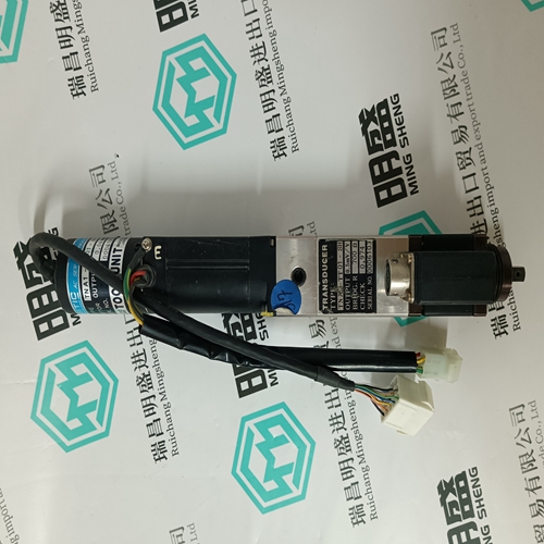
Home > Product > DCS control system > TRICONEX EPI3382 Control card
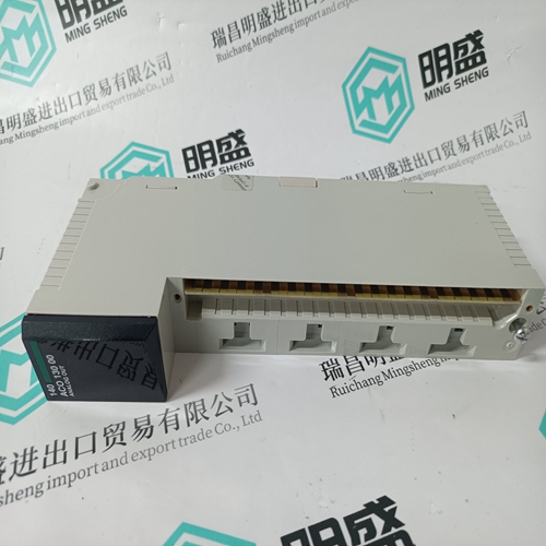
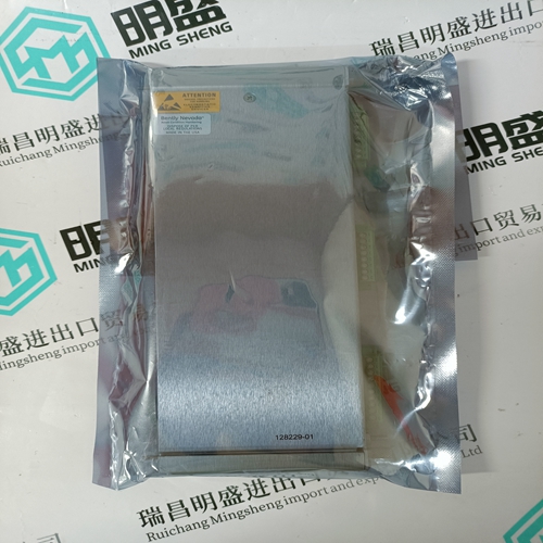
TRICONEX EPI3382 Control card
- Product ID: EPI3382
- Brand: TRICONEX
- Place of origin: The United States
- Goods status: new/used
- Delivery date: stock
- The quality assurance period: 365 days
- Phone/WhatsApp/WeChat:+86 15270269218
- Email:stodcdcs@gmail.com
- Tags:TRICONEX EPI3382Control card
- Get the latest price:Click to consult
The main products
Spare parts spare parts, the DCS control system of PLC system and the robot system spare parts,
Brand advantage: Allen Bradley, BentlyNevada, ABB, Emerson Ovation, Honeywell DCS, Rockwell ICS Triplex, FOXBORO, Schneider PLC, GE Fanuc, Motorola, HIMA, TRICONEX, Prosoft etc. Various kinds of imported industrial parts
TRICONEX EPI3382 Control card
The motor can now be coupled to the machine if it was previously decoupled. 7. Stopping in an emergency-off situation: The safety limit switch should be mounted with sufficient distance to the limit stop, and the cams should be checked for sufficient length. Run the axes individually and at maximum speed onto the safety limit switch. Measure the stopping distance and check to see whether it was long enough. This task should be performed in both directions of a vertical axis. 8. Drift compensation: No compensation is neeeded with torque-controlled or slave drives! Using the adjustment screw, „ZERO ADJUST“, on the right-hand side at the bottom on the front, the zero-point drift can be set to speed zero, if a set-point of 0 volts is given at the corresponding plug-in terminal in the open position-control circuit. The speed drift is determined by observing axis movement or motor speed, or it can, if necessary, be measured at terminal Tsense. The interaction of the NC, feed drive, position measurements and coupled-in mechanics in the position and speed control loops is outlined in Fig. 75 using the example of a direct measuring system.
Matching to the NC
1. Operational sign of the path feed direction (machine coordinates) Operate the drive, at first, with the set-point encoder box. It is necessary to check whether the path feed direction indicated by the NC agrees with the actual direction of movement. If it does not, then it should be re-poled according to Chapter 2.1, page 17, in the direction of rotation. 2. Check the drift of the drive with zero speed set-point: If the axis moves with zero speed set-point, then using the potentiometer „ZERO ADJ“ on the front plate, set the rotation movement of the axis to zero with control cabinet end temperature. This should always be checked after initial commissioning and after the servo drive module has been exchanged. 3. Checking the position control loop: – Using the set-point encoder box, enter low positive speed set-point voltages of a few mV at the set-point input of the servo-module and run the axis. – The controller must emit a negative set-point voltage for the axis. The polarity of the actual position value must be changed, if this is not the case. 4. Switching and clamping off the set-point box. Connect set-point line and the controller enable from the controller to the servo drive module. 5. Check input weightings: The speed set-point input weightings of the servo drive module must be rated in such a way that maximum motor speed or maximum sliding carriage speed is achieved with 80 to 90% of maximum NC output voltage. This ensures that the position controller remains within the active range, even with minor overshooting in the NC output voltage. Input ratings can, if needed, be changed on the programming module in accordance with the data in Chapter 3.2. 6. Check set-point smoothing: The NC rated speed set-point values may not exceed the alternating current share of
