Home > Product > DCS control system > ABB 3BHB040969R0002 Output personality card
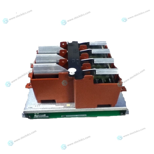
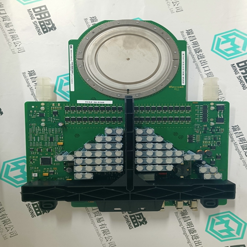
ABB 3BHB040969R0002 Output personality card
- Product ID: 3BHB040969R0002
- Brand: ABB
- Place of origin: The Swiss
- Goods status: new/used
- Delivery date: stock
- The quality assurance period: 365 days
- Phone/WhatsApp/WeChat:+86 15270269218
- Email:xiamen2018@foxmail.com
- Tags:ABB3BHB040969R0002Output personality card
- Get the latest price:Click to consult
ABB 3BHB040969R0002 Output personality card
Data is transferred over the backplane using the module’s input and output images. The module is configured with an eight-word input image and a sevenword output image. The module and the Flex processor use these images to page data and commands. The input image is set (written) by the module and is read by the Flex processor. The output image is set (written) by the Flex processor and read by the module. The following illustration shows this relationship.The module’s program is responsible for setting the block identification code used to identify the data block written and the block identification code of the block it wants to read from the processor. User configuration information determines the read (Read Start Register) and write (Write Start Register) locations in the virtual Modbus database and the amount of data transferred (Read Register Count and Write Register Count). Each read and write operation transfers a six-word data area. The processor read operation contains a twoword header that defines the block identification code of the read data and the block identification code of the write block requested.
The module and the processor constantly monitor input and output images.
How does either one know when a new block of data is available? Recognizing a change in the header information of the image (word 0) solves the problem. For example, when the module recognizes a different value in the first word of the output image, new processor write data is available. When the processor recognizes a new value in the first word of the input image, new processor read data is available. This technique requires the storage of the previously processed data block identification code.The new data contained in the input image (words 2 to 7) is copied to the offset in the processor’s user data file. The last_read_block_code storage register in the processor is updated with the new read_block_code.
The following steps outline this diagram:
1 During program initialization, the write and read block identification codes are set to one.
2 The last block write variable is set to zero.
3 The program copies the first six-word block of the virtual Modbus database starting at the user defined Read Start Register to the input image (words 2 to 7). It then sets the current write block code in word 1 of the input image. To "trigger" the write operation, the program places the current read block code into word 0 of the input image.


Brand display
ABB、GE/FUANC、FOXBORO、TRICONEX 、BENTLY、A-B、EMERSON 、MOTOROLA、XYVOM、HONEYWELL 、REXROTH、KUKA、NI、DEIF、Yokogawa、WOODWARD、Reliance Electric、SCHNEIDER 、MOOG、PROSOFT、KOLLMORGEN、ICS TRIPLEX、HIMA。
