Home > Product > DCS control system > ABB 3BHE022287R0001 Input electronic card
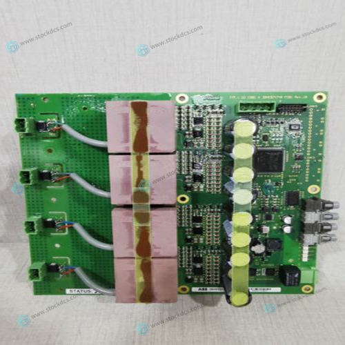
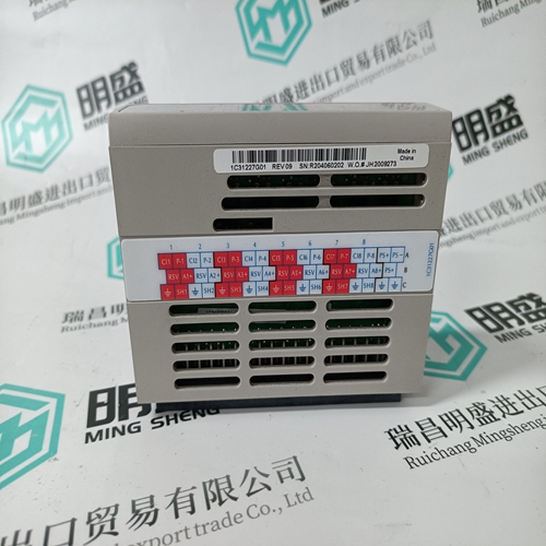
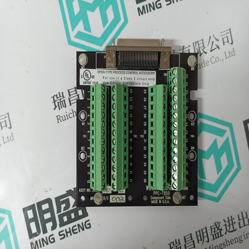
ABB 3BHE022287R0001 Input electronic card
- Product ID: 3BHE022287R0001
- Brand: ABB
- Place of origin: The Swiss
- Goods status: new/used
- Delivery date: stock
- The quality assurance period: 365 days
- Phone/WhatsApp/WeChat:+86 15270269218
- Email:xiamen2018@foxmail.com
- Tags:ABB3BHE022287R0001Input electronic card
- Get the latest price:Click to consult
ABB 3BHE022287R0001 Input electronic card
Data is transferred between the processor and the module using the block identification codes of 1 to 666. The other block codes control the module from the processor’s ladder logic. They are implemented when the ladder logic needs to control the module. In order to use one of the blocks, the ladder logic inserts the data and code in the output image of the module. The data should be set before the code is placed in the block. This operation should be performed after the receipt of a new write block from the module. A discussion of each set of codes is given in the following topics.Slave status data sends status information of each slave device on a master port. This data is passed to the controller through the user database. The location of this data is set with the Slave List Pointer parameter.
Slaves are defined to the system
when the module initializes the master command list. Each slave defined will be set to a state of one in this initial step. If the master port fails to communicate with a slave device (retry count expired on a command), the master will set the state of the slave to a value of 2 in the status table. This suspends communication with the slave device for a user specified scan count (Error Delay Counter value in the module configuration for each port). Each time a command in the list is scanned that has the address of a suspended slave, the delay counter value will be decremented. When the value reaches zero, the slave state will be set to one. This will enable polling of the slave.Ladder logic can be written to override the value in the slave status table to enable the slave (state value of 1) by sending a special block. Slaves are enabled using block 3001 (write block in output image). This block contains the slave node addresses to enable. The following table describes the format for this block.
When the module receives one of these blocks
it examines word 0 of the output image. This word defines the number of commands contained in the block. The command count is determined by subtracting 5000 from the word value. This permits the controller to set from one to six commands into the command queue. The indexes submitted in the block should be valid for the command list. After the module determines the number of commands to be considered, it inserts each command in the command queue.These control blocks are sent from the processor to the module to execute one or more commands in the module's command list out the DF1 master port. Commands selected for execution need not have the Enable Code set (1 or 2) but must be valid commands.


Brand display
ABB、GE/FUANC、FOXBORO、TRICONEX 、BENTLY、A-B、EMERSON 、MOTOROLA、XYVOM、HONEYWELL 、REXROTH、KUKA、NI、DEIF、Yokogawa、WOODWARD、Reliance Electric、SCHNEIDER 、MOOG、PROSOFT、KOLLMORGEN、ICS TRIPLEX、HIMA。
