Home > Product > PLC programmable module > ICS TRIPLEX 9100 base
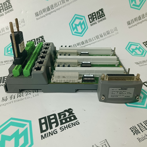
ICS TRIPLEX 9100 base
- Goods status: new/used
- Delivery date: stock
- The quality assurance period: 365 days
- Phone/WhatsApp/WeChat:+86 15270269218
- Email:stodcdcs@gmail.com
- Tags:ICS TRIPLEX9100base
- Get the latest price:Click to consult
The main products
Spare parts spare parts, the DCS control system of PLC system and the robot system spare parts,
Brand advantage: Allen Bradley, BentlyNevada, ABB, Emerson Ovation, Honeywell DCS, Rockwell ICS Triplex, FOXBORO, Schneider PLC, GE Fanuc, Motorola, HIMA, TRICONEX, Prosoft etc. Various kinds of imported industrial parts
ICS TRIPLEX 9100 base
Many numeric controls change their output voltages only gradually in agreement with the computers cycle time. Since the drives attempt to follow every set-point gradation of the step-function, the effects are – unnecessary motor power loss, – increased machine stress, – noise development during acceleration and braking, and, – machine vibrations during interpolation.
If such disruptive, harmonic vibrations should appear on the tacho signal - can be measured at terminal Tsense of the servo drive module - as a result of the set-point voltage emitted by the NC (step function) - can be measured at input of set-points at terminals E1-E2, E3 or E4 of the servo drive module - then it is possible to achieve a reduction in the oscillations by soldering a capacitor (set-point smoothing) on programming module MOD, in accordance with Chapter 3.2. It should be, however, noted that a big capacitor can reduce the dynamics of the position control loops and thereby also make it less responsive (smaller Kv factor).
This is increased until a stable and rapid response of the position controller is achieved (see information in NC User Handbook).
Checking Drive Configuration
These tests are recommended to the machine manufacturer when the drives are initially commissioned or with prototype commissioning. They serve to determine whether the drives have been sufficiently adjusted to meet the demands made by the construction of the machine or plant. An oscilloscope with memory or an analogue recorder are needed for the measurements. Measurements must be taken in both directions. 1. The stability of the control loop The drive is operated using the set-point battery box, in accordance with Diagram 74. Should mechanical oscillations occur right after the servo drive is switched on via the controller enable while the equipment is still standing still or in the movement of the drives, then the mechanics have not been sufficiently secured against oscillations. Possible causes: – The coupling of the load mass to the motor shaft is too elastic. This causes resonance vibrations with the outside inert mass.
The external inert mass is too great. The speed control loop becomes unstable. Generally, the ratio of the motor’s own mass to external mass at the motor shaft equals 1:5. – Instability of the machine’s mechanics. – Low frequency oscillations at position due to changes in the friction ratio which are not constant (stick-slip-effect).