Home > Product > PLC programmable module > ICS TRIPLEX 9802*3 base

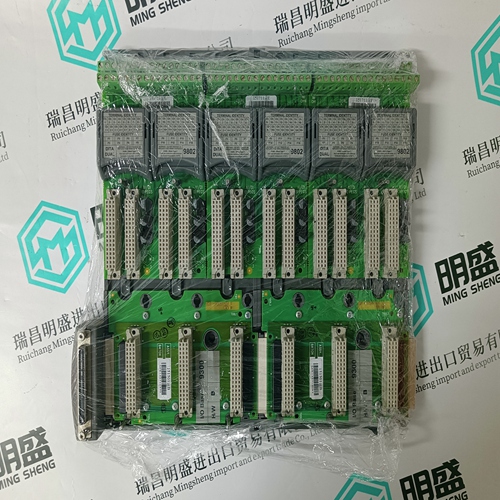
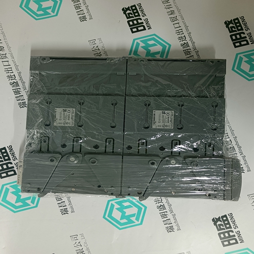
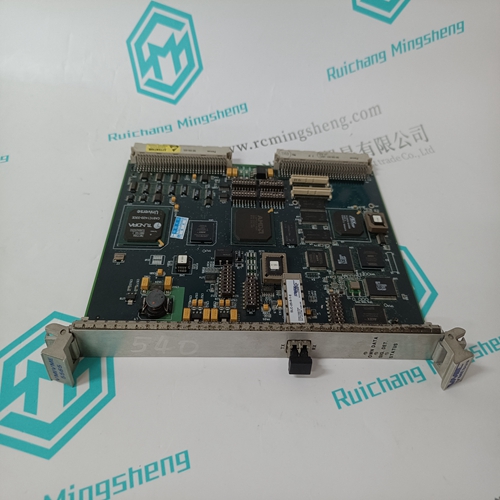
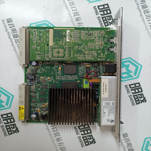
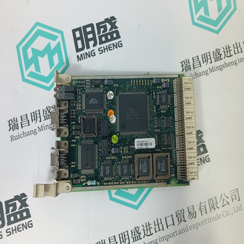
ICS TRIPLEX 9802*3 base
- Product ID: 9802*3
- Brand: ICS TRIPLEX
- Place of origin: the United States
- Goods status: new/used
- Delivery date: stock
- The quality assurance period: 365 days
- Phone/WhatsApp/WeChat:+86 15270269218
- Email:stodcdcs@gmail.com
- Tags:ICS TRIPLEX 9802*3base
- Get the latest price:Click to consult
The main products
Spare parts spare parts, the DCS control system of PLC system and the robot system spare parts,
Brand advantage: Allen Bradley, BentlyNevada, ABB, Emerson Ovation, Honeywell DCS, Rockwell ICS Triplex, FOXBORO, Schneider PLC, GE Fanuc, Motorola, HIMA, TRICONEX, Prosoft etc. Various kinds of imported industrial parts
ICS TRIPLEX 9802*3 base
These oscillations can be verified by measuring the tachometer signal at terminal Tsense using either an oscilloscope or a recorder. Oscillations with low amplitudes require a fine adjustment of the oscilloscope or a measurement at terminal „MA“. If the mechanics of the machine can definitely be excluded as the source, or if a structural alteration in the mechanics is too expensive, then a special drive optimization by changing the values of programming module MOD can bring about an improvement. This can, however, also simultaneously bring about a deterioration in the dynamics at the machine axes. In this case, INDRAMAT’s customer service should be consulted prior to changing the wiring of programming module MOD. When calling in a problem to INDRAMAT’s customer service, the following information is important: – Mechanical construction of the coupling to the servo motor and the entire axes? – Outside moments of inertia coupled in as relate to motor shaft? – Continuous or intermittent oscillations and at what stage of operation? – Size of the oscillation amplitudes of the voltage measured in volt peak-peak? – Duration or frequency of vibrations?
Basic torque at different speeds.
Load moment can be measured at terminal „MA“ of the servo drive module, where the current set-point can be read, as the current consumption of the servo drive is a measurement for the given torque. The corresponding current is calculated A comparison of this Value I with the Value I(dN) of the motor’s permanent or rated current, to be found listed either on the table in Fig. 95 in Chapter 10.1., or on the rating plate of the motor, indicates the torque load of the servo-drive. These measurements are to be taken at minimum and maximum feed speed, run during a later stage of operation during processing. The current measured at MA should not be greater than 60% of the motor’s permanent current. If the current measured should be greater, then the possible causes for an excessive basic torque, despite correct construction, can be: – axis clamp not released – mechanical jams at the drive axis – insufficient lubrication – increased adhesive or sliding friction at the carriage guides – unfavorably adjusted weight compensation The corresponding torque of motor current I of the measured voltage UMA at terminal MA can be calculated as follows:Rapid Return Motion Torque Measure as described under 2. The current at MA should not exceed 75% of the motor’s rated current. Should the current exceed this, then the possible causes for excessive rapid return motion torque, despite proper construction, can be: – unfavorable hydraulic or pneumatic weight compensation – excessive liquid friction in the gear-tooth system of an attached oilbath gearbox – a breakdown in the lubricating film of the sliding guide – poor ball return in the nut of the ball roll spindle.