Home > Product > PLC programmable module > ICS TRIPLEX 9852*3 base
ICS TRIPLEX 9852*3 base
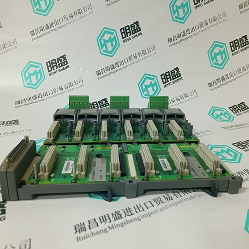
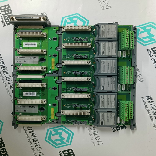
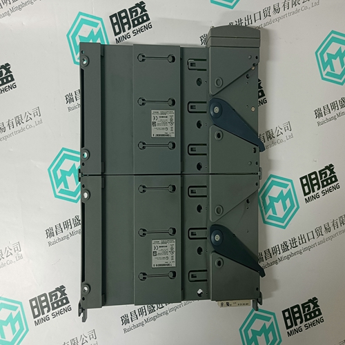
- Product ID: 9852*3
- Brand: ICS TRIPLEX
- Place of origin: the United States
- Goods status: new/used
- Delivery date: stock
- The quality assurance period: 365 days
- Phone/WhatsApp/WeChat:+86 15270269218
- Email:stodcdcs@gmail.com
- Tags:ICS TRIPLEX 9852*3base
- Get the latest price:Click to consult
The main products
Spare parts spare parts, the DCS control system of PLC system and the robot system spare parts,
Brand advantage: Allen Bradley, BentlyNevada, ABB, Emerson Ovation, Honeywell DCS, Rockwell ICS Triplex, FOXBORO, Schneider PLC, GE Fanuc, Motorola, HIMA, TRICONEX, Prosoft etc. Various kinds of imported industrial parts
ICS TRIPLEX 9852*3 base
Adjusting weight compensation with vertical axes The weight should be compensated so that the motor current input with the up and down motions of the axes always retains the same minimum value. The adjustment should be checked at feed and rapid return motion speeds. 5. Acceleration times In this case, speed as a function of time (run-up curve) when accelerating and braking to the necessary speed, is recorded with either an oscilloscope or a recorder. Speed output serves as the measurement signal (tacho) at terminal „Tsense“. The evaluation cw in V/ A depends upon the type of motor and is listed in Fig. 95 of Chapter 10.1. The corresponding acceleration moment, or current can simultaneously be recorded at terminal „MA“. (The evaluation in V/ A is dependent upon the servo drive module and can be found in Chapter 10.2). When operating the NC in controlled position, the torque should only reach its maximum value in the first phase of the acceleration/braking procedure, while remaining below maximum value over the remaining period of time in order to maintain sufficient reserves and avoid overshooting its position. Acceleration and braking times must be measured and compared to the design data.
Controlling Feedback Energy
– Accelerate all the drives connected to the supply unit to maximum speed and then initiate an emergency off. A shutdown of the power section via the ready-to-operate contact Bb1 of the supply unit cannot take place. – Run the drives for at least 15 minutes in an operative load cycle during which the highest mean braking energy of all drives can be expected. In this case as well, the power section should not be switched off via the ready-to-operate contact Bb1 of the supply unit. Should a switch off nonethless occur in either of the two cases, then the supply lay-out must be corrected (see supply lay-out description). It is possible that a different supply module or an additional modular unit (TBM or TCM) is required. This depends upon the drive type connected.
In the event of a problem within the machine or the facility, it can be advantageous to proceed in accordance with the following steps to quickly eliminate faults and resume operation: 1. Determine nature of problem. (Can improper operation or incorrect installation be eliminated from the start?) 2. Follow the effects of the fault and limit the source of the fault. 3. Determine direct cause of fault, defective part. 4. Correct error and control operation.