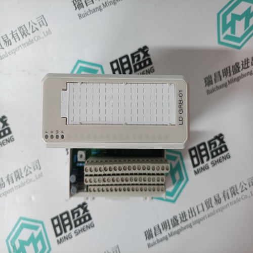
Home > Product > DCS control system > REF542plus Operation panel
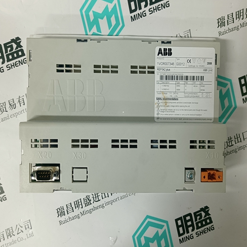
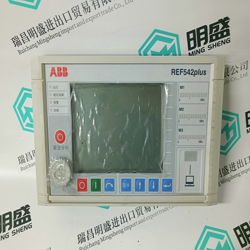
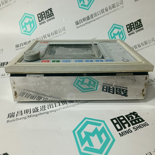
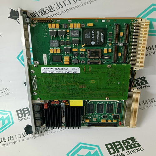
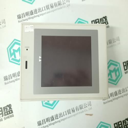
REF542plus Operation panel
- Product ID: REF542plus
- Brand: ABB
- Place of origin: The Swiss
- Goods status: new/used
- Delivery date: stock
- The quality assurance period: 365 days
- Phone/WhatsApp/WeChat:+86 15270269218
- Email:stodcdcs@gmail.com
- Tags:REF542plusOperation panel
- Get the latest price:Click to consult
The main products
Spare parts spare parts, the DCS control system of PLC system and the robot system spare parts,
Brand advantage: Allen Bradley, BentlyNevada, ABB, Emerson Ovation, Honeywell DCS, Rockwell ICS Triplex, FOXBORO, Schneider PLC, GE Fanuc, Motorola, HIMA, TRICONEX, Prosoft etc. Various kinds of imported industrial parts
REF542plus Operation panel
Possible fault causes and measures:
– Link circuit throttle connection of the supply module not allocated
(does not apply to TVM 1 and 2).
➞ Check whether the throttle on the link circuit throttle connecting
terminals 1L+, 2L+, 1L-, 2L- has been properly attached, or whether
a wire strap has been clamped on.
– No mains power
➞ Check three-phase mains power connection
(Look for fault between mains connection and supply unit.)
➞ Check the mains contactor control
– Mains voltage too low
➞ Test mains power at connecting terminals L1, L2, L3 of the supply
module.
➞ Incorrect transformer connection or fault in mains
– Mains power phase missing
➞ Check and re-measure 3-phase mains power at the supply module
➞ Check link circuit short-circuit
➞ Check mains fuse – Only applies to KDV2, 3 and 4:
No right rotational field present (fault only occurs the first time the
machine or the drives are connected to the mains).
➞ Check rotational field direction at connecting terminals L1, L2, L3 of
the supply module (e.g., with the use of rotational field measuring
equipment, or the succession of phases with an oscilloscope).
Exchange leads L1 and L2 on the supply module if there is no right
rotational field.
Absolute attention must be paid that mains auxiliary power connections L1, or L3 remain connected inphase to power connections L1,
or L3 of the supply module KDV, in accordance with connection
plans.
– Supply module defective
➞ Remove intermediate circuit busbars and bus cable X1 between the
supply module and the driving module, then repeat the above check.
If no fault can be found now, and the LED „power OK“ of the supply
module is lit up, then the fault is in the connected drive modules.
➞ Exchange supply modules.
LED Diagnostic Displays
If the fault cannot be located using the messages received at the terminal strips, then the diagnostic displays on the front side of each modular unit, beginning with the supply module, need to be checked. This can be quickly accomplished by using the figures in Chapter 9. The most practical thing to do first is to check to see whether the light emitting diodes are displaying the condition „working“, as indicated in these figures. In the presence of a malfunction, the green lamps generally light up, while the red lamps should be off. Clearing a Fault: A reset-key makes it possible to clear all stored fault messages without having to shutdown the mains auxiliary power/control voltage on the supply module. It is located on the front on the right hand side at the top above the diagnostics display. The fault messages are automatically cleared and reset after the control voltage has been turned back on. If the diagnostic displays on the supply or driving modules indicate a fault, then the following measures can be taken individually
