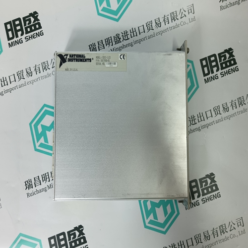
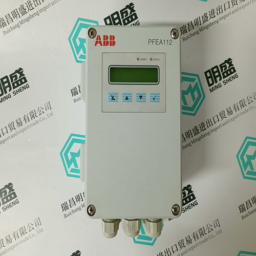
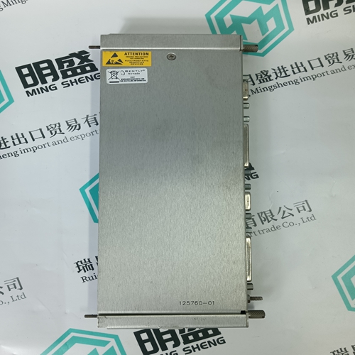
Home > Product > DCS control system > HONEYWELL SC-TCMX01 51307198-175 Ladder module
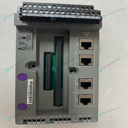
HONEYWELL SC-TCMX01 51307198-175 Ladder module
- Product ID: SC-TCMX01 51307198-175
- Brand: HONEYWELL
- Place of origin: The Swiss
- Goods status: new/used
- Delivery date: stock
- The quality assurance period: 365 days
- Phone/WhatsApp/WeChat:+86 15270269218
- Email:stodcdcs@gmail.com
- Tags:HONEYWELLSC-TCMX0151307198-175Ladder module
- Get the latest price:Click to consult
HONEYWELL SC-TCMX01 51307198-175 Ladder module
The MVME162 is a double-high VMEmodule equipped with an MC68LC040 or optional MC68040 microprocessor. (The MC68040 microprocessor has a floating-point coprocessor; the MC68LC040 does not.) The MVME162 has 1MB, 4MB, or 8MB of parity-protected DRAM; 512KB SRAM (with battery backup); a TOD clock (with battery backup); an optional LAN Ethernet transceiver interface with DMA, two serial ports (EIA-232-D and EIA-232-D/EIA-530); six tick timers with watchdog timer(s); optional SCSI bus interface with DMA; VMEbus interface (local bus to VMEbus/VMEbus to local bus, with A16/A24/A32, D8/D16/D32 bus widths and a VMEbus system controller)
Input/Output
Input/Output (I/O) signals are routed through backplane connector P2. A P2 adapter board or LCP2 adapter board routes the signals and grounds from connector P2 to an MVME712 series transition module (MVME712-12, MVME712-13, MVME712A, MVME712AM, or MVME712M). The transition module routes the signals to the appropriate configuration headers and industry-standard connectors. Refer to the MVME712-12, MVME712-13, MVME712A, MVME712AM, and MVME712B Transition Modules and LCP2 Adapter Board User’s Manual or the MVME712M Transition Module and P2 Adapter Board User’s Manual for more information.
Notes
When used with the MVME162, only serial ports 2 and 4 on the MVME712 are available for use. Serial ports 1 and 3 and the printer port are not connected to any MVME162 circuits and should not be used. An I/O device may be connected to serial port 1 (or 2) on the MVME162 or to serial port 2 (or 4) on the MVME712, but not both. (That is, if an I/O device is connected to MVME162 port 1, no other I/O device should be connected to MVME712 port 2; they are functionally the same port.)


Professional seller
Professional sales of major electrical brand products in the world
Overseas direct purchase of products, authentic inventory, price concessions
After sales warranty, complete models, same products, different prices and services
