Home > Product > DCS control system > TRICONEX 4000103-510N cable
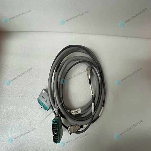
TRICONEX 4000103-510N cable
- Product ID: 4000103-510N
- Brand: TRICONEX
- Place of origin: The United States
- Goods status: new/used
- Delivery date: stock
- The quality assurance period: 365 days
- Phone/WhatsApp/WeChat:+86 15270269218
- Email:xiamen2018@foxmail.com
- Tags:TRICONEX4000103-510Ncable
- Get the latest price:Click to consult
TRICONEX 4000103-510N cable
Port B of the MVME162’s Z85230 serial communications controller is configurable via a serial interface module (SIM) which is installed at connector J10 on the MVME162 board. Four serial interface modules are available: ❏ EIA-232-D (DCE and DTE) ❏ EIA-530 (DCE and DTE) You can change Port B from an EIA-232-D to an EIA-530 interface (or viceversa) by mounting the appropriate serial interface module. Port B is routed (via the SIM at J10) to the 25-pin DB25 front panel connector marked SERIAL PORT 2. For the location of SIM connector J10 on the MVME162, refer to Figure 2-1. Figure 2-2 illustrates the secondary side (bottom) of a serial interface module, showing the J1 connector which plugs into SIM connector J10 on the MVME162. Figure 2-3 (sheets 3-6), Figure 2-4 (sheets 3-4), and Figure 2-5 illustrate the configurations available for Port B.
For the part numbers of the serial interface modules
refer to Table 2-1. The part numbers are ordinarily printed on the primary side (top) of the SIMs, but may be found on the secondary side in some versions. If you need to replace an existing serial interface module with a SIM of another type, go to Removal of Existing SIM below. If there is no SIM on the main board, skip to Installation of New SIM.Removal of Existing SIM 1. Each serial interface module is retained by two 4-40 x 3 /16 ” Phillips-head screws in opposite corners. Remove the two screws and store them in a safe place for later use. 2. Grasp opposite sides of the SIM and gently lift straight up.
Installation of New SIM
1. Observe the orientation of the connector keys on SIM connector J1 and MVME162 connector J10. Turn the SIM so that the keys line up and place it gently on connector J10, aligning the mounting holes at the SIM corners with the matching standoffs on the MVME162. 2. Gently press the top of the SIM to seat it on the connector. If the SIM does not seat with gentle pressure, recheck the orientation. If the SIM connector is oriented incorrectly, the mounting holes will not line up with the standoffs. Caution Do not attempt to force the SIM on if it is oriented incorrectly. 3. Place the two 4-40 x 3 /16” Phillips-head screws that you previously removed (or that were supplied with the new SIM) into the two oppositecorner mounting holes. Screw them into the standoffs but do not overtighten them.

Professional seller
Professional sales of major electrical brand products in the world
Overseas direct purchase of products, authentic inventory, price concessions
After sales warranty, complete models, same products, different prices and services