Home > Product > PLC programmable module > SST 5136-DN-PC
SST 5136-DN-PC
- Product ID: 5136-DN-PC
- Brand: SST
- Place of origin: the United States
- Goods status: new/used
- Delivery date: stock
- The quality assurance period: 365 days
- Phone/WhatsApp/WeChat:+86 15270269218
- Email:stodcdcs@gmail.com
- Tags:SST 5136-DN-PCInterface module
- Get the latest price:Click to consult
The main products
Spare parts spare parts, the DCS control system of PLC system and the robot system spare parts,
Brand advantage: Allen Bradley, BentlyNevada, ABB, Emerson Ovation, Honeywell DCS, Rockwell ICS Triplex, FOXBORO, Schneider PLC, GE Fanuc, Motorola, HIMA, TRICONEX, Prosoft etc. Various kinds of imported industrial parts
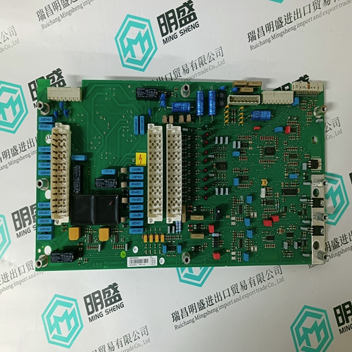
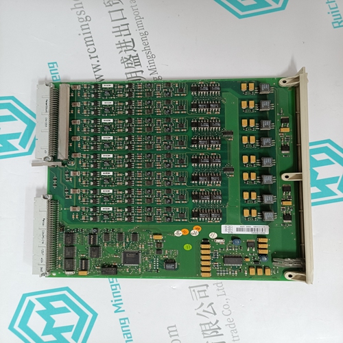
SST 5136-DN-PC Interface module
Depending upon the configuration, connect test equipment to the I/O terminals. FCO101 - This FCO has one 1-5 Volt analog input (AIN1), and one 4-20 mA analog output (AOUT1) configured. To verify both of these outputs, and to simulate an analog input for subsequent steps, jumper the terminals shown below. Connect a 250 ohm range resistor across the terminals shown below to convert the 4- 20 mA output to a 1-5 volt input. This will tie the valve output (horizontal bargraph) back in the loop as the process input (P bargraph). Refer to Section 8 as necessary.
• Remove power from all wires and terminals before working on equipment. • In potentially hazardous atmosphere, remove power from equipment before connecting or disconnecting power, signal, or other circuit. • Observe all pertinent regulations regarding installation in hazardous area.
Apply power to the controller. Upon power up a two step test is automatically performed on the alphanumeric display to light all segments. ‘WAIT’ will then appear on the alphanumeric display while the controller performs power-up diagnostics. If a power-up diagnostic test fails, an error code will be displayed on the alphanumeric display. Refer to Sections 11.3 and 11.4 for troubleshooting error codes. If WAIT remains displayed for more than 1 minute, the controller is not powering up correctly and power connections should be checked for loose wiring. 10.1.2 Configuration 1. Determine the current configuration; refer to Section 10.0 above. Then perform one of the following steps. To load FCO101, go to step 2.
IMPORTANT
Loading FCO101 will overwrite the current configuration and any entries made since shipment. Skip step 2 if the installed configuration is to be retained. To proceed with the installed configuration, go to Section 10.1.3. 2. To load FCO101 either locally or to download it from a PC running the Graphical Configuration Utility, refer to Section 2.7 for a procedure and to Section 4 for the block diagram and parameter values. 3. Edit the configuration as desired. Refer to Section 10.1.5 Modifying an FCO. 10.1.3 Input/Output Press the D button on the faceplate to scroll through Loop01.S (Setpoint), Loop01.V (Valve Output), and Loop01.P (Process Input). Note from the FCO101 block diagram, that INPUT P is configured as the output from function block AIN1, INPUT S is configured as the output of function block SETPT, and INPUT V is configured as the output of function block A/M.