Home > Product > DCS control system > TRICONEX 8111N Industrial rack
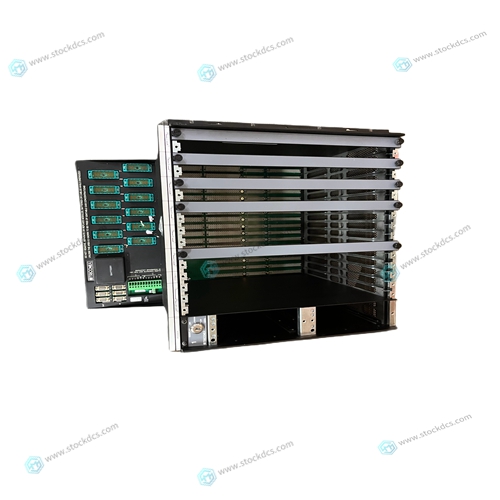
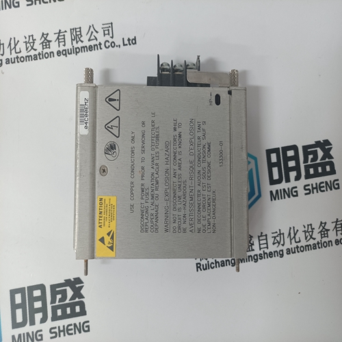
TRICONEX 8111N Industrial rack
- Product ID: 8111N
- Brand: TRICONEX
- Place of origin: The United States
- Goods status: new/used
- Delivery date: stock
- The quality assurance period: 365 days
- Phone/WhatsApp/WeChat:+86 15270269218
- Email:xiamen2018@foxmail.com
- Tags:TRICONEX8111NIndustrial rack
- Get the latest price:Click to consult
TRICONEX 8111N Industrial rack
The following sections discuss the installation of IndustryPacks (IPs) on the MVME162, the installation of the MVME162 into a VME chassis, and the system considerations relevant to the installation. Before installing IndustryPacks, ensure that the serial ports and all header jumpers are configured as desired. IP Installation on the MVME162 Up to four IndustryPack (IP) modules may be installed on the MVME162. Install the IPs on the MVME162 as follows: 1. Each IP has two 50-pin connectors that plug into two corresponding 50- pin connectors on the MVME162: J2/J3, J7/J8, J13/J14, J18/J19. See Figure 2-1 for the MVME162 connector locations. – Orient the IP(s) so that the tapered connector shells mate properly. Plug IP_a into connectors J2 and J3; plug IP_b into J7 and J8. Plug IP_c into J13 and J14; plug IP_d into J18 and J19. If a double-sized IP is used, plug IP_ab into J2, J3, J7, and J8; plug IP_cd into J13, J14, J18, and J19.
Four additional 50-pin connectors
are provided behind the MVME162 front panel for external cabling connections to the IP modules. There is a one-to-one correspondence between the signals on the cabling connectors and the signals on the associated IP connectors (i.e., J6 has the same IP_a signals as J2; J5 has the same IP_b signals as J7; J17 has the same IP_c signals as J13; and J16 has the same IP_d signals as J18. – Connect user-supplied 50-pin cables to J6, J5, J17, and J16 as needed. Because of the varying requirements for each different kind of IP, Motorola does not supply these cables. – Bring the IP cables out the narrow slots in the MVME162 front panel and attach them to the appropriate external equipment, depending on the nature of the particular IP(s).
MVME162 Module Installation
With EPROM and IndustryPacks installed and headers properly configured, proceed as follows to install the MVME162 in the VME chassis: 1. Turn all equipment power OFF and disconnect the power cable from the AC power source.
2. Remove the chassis cover as instructed in the user’s manual for the equipment. 3. Remove the filler panel from the card slot where you are going to install the MVME162. – If you intend to use the MVME162 as system controller, it must occupy the leftmost card slot (slot 1). The system controller must be in slot 1 to correctly initiate the bus-grant daisy-chain and to ensure proper operation of the IACK daisy-chain driver. – If you do not intend to use the MVME162 as system controller, it can occupy any unused double-height card slot.

Professional seller
Professional sales of major electrical brand products in the world
Overseas direct purchase of products, authentic inventory, price concessions
After sales warranty, complete models, same products, different prices and services