Home > Product > Robot control system > Rolls-royce SLIO02 Analog quantity counting module

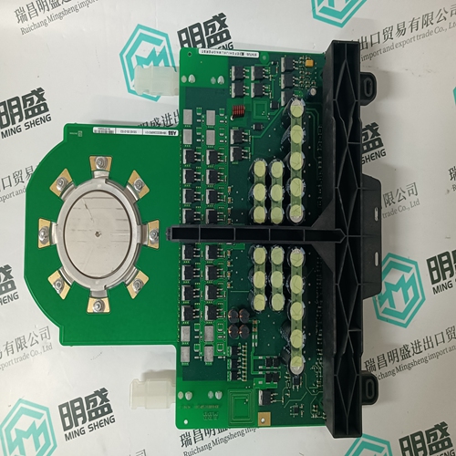
Rolls-royce SLIO02 Analog quantity counting module
- Product ID: SLIO02
- Brand: Rolls-royce
- Place of origin: The United States
- Goods status: new/used
- Delivery date: stock
- The quality assurance period: 365 days
- Phone/WhatsApp/WeChat:+86 15270269218
- Email:xiamen2018@foxmail.com
- Tags:Rolls-royceSLIO02Analog quantity counting module
- Get the latest price:Click to consult
Rolls-royce SLIO02 Analog quantity counting module
In specifying parameters for serial binary data interchange between DTE and DCE devices, the EIA-530 standard assumes the use of balanced lines, except for the Remote Loopback, Local Loopback, and Test Mode lines, which are single-ended. Balanced-line data interchange is generally employed in preference to unbalanced-line data interchange where any of the following conditions prevail: ❏ The interconnection cable is too long for effective unbalanced operation. ❏ The interconnection cable is exposed to extraneous noise sources that may cause an unwanted voltage in excess of ±1V measured differentially between the signal conductor and circuit ground at the load end of the cable, with a 50Ω resistor substituted for the transmitter. ❏ It is necessary to minimize interference with other signals. ❏ Inversion of signals may be required (e.g., plus polarity MARK to minus polarity MARK may be achieved by inverting the cable pair). EIA-530 interface transmitter and receiver parameters applicable to the MVME162 are listed in Tables A-5 and A-6.
Proper Grounding
An important subject to consider is the use of ground pins. There are two pins labeled GND. Pin 7 is the signal ground and must be connected to the distant device to complete the circuit. Pin 1 is the chassis ground, but it must be used with care. The chassis is connected to the power ground through the green wire in the power cord and must be connected to be in compliance with the electrical code. The problem is that when units are connected to different electrical outlets, there may be several volts of difference in ground potential. If pin 1 of each device is interconnected with the others via cable, several amperes of current could result. This condition may not only be dangerous for the small wires in a typical cable, but may also produce electrical noise that causes errors in data transmission. That is why Tables A-1 and A-4 show no connection for pin 1. Normally, pin 7 (signal ground) should only be connected to the chassis ground at one point; if several terminals are used with one computer, the logical place for that point is at the computer. The terminals should not have a connection between the logic ground return and the chassis.
Getting Started
This section supplies an overview of startup procedures applicable to the MVME172LX. Equipment requirements, directions for unpacking, and ESD precautions that you should take complete the section. Overview of Installation Procedure The following table lists the things you will need to do to use this board and tells where to find the information you need to perform each step. Be sure to read this entire chapter, including all Caution and Warning notes, before you begin.

Professional seller
Professional sales of major electrical brand products in the world
Overseas direct purchase of products, authentic inventory, price concessions
After sales warranty, complete models, same products, different prices and services