Home > Product > Robot control system > TDK FAW05-5R0 Robot card
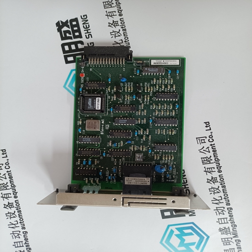
TDK FAW05-5R0 Robot card
- Product ID: FAW05-5R0
- Brand: TDK
- Place of origin: The United States
- Goods status: new/used
- Delivery date: stock
- The quality assurance period: 365 days
- Phone/WhatsApp/WeChat:+86 15270269218
- Email:stodcdcs@gmail.com
- Tags:TDKFAW05-5R0Robot card
- Get the latest price:Click to consult
TDK FAW05-5R0 Robot card
ock Header (J11) J11 selects the speed of the IP bus clock. The IP bus clock speed may be either 8MHz or the speed of the local bus clock (30MHz for the MC68060, 32MHz for the MC68LC060). The default factory configuration has a jumper installed on J11 pins 1 and 2, denoting an 8MHz clock. If the jumper is installed on J11 between pins 2 and 3, the IP bus clock speed matches that of the MC68060 or MC68LC060 bus clock (30/32MHz), thus allowing the IP module to run with a 30/32MHz MPU. Whether the setting is 8MHz or 30/32MHz, all IP ports operate at the same speed.
minator Enable Header (J12) The MVME172LX provides terminators for the SCSI bus. The SCSI terminators are enabled/disabled by a jumper on header J12.
SRAM Backup Power Source Select Header
Header J14 determines the source for onboard static RAM backup power on the MVME172LX. The following backup power configurations are available for onboard SRAM through header J14. In the factory configuration, the VMEbus +5V standby voltage serves as primary and secondary power source (the onboard battery is disconnected). Note For MVME172LXs without the optional VMEbus interface (i.e., without the VMEchip2 ASIC), you must select the onboard battery as the backup power source. ! Caution Removing all jumpers may temporarily disable the SRAM. Do not remove all jumpers from J14, except for storage.
IP Bus Strobe Select Header
Some IP bus implementations make use of the Strobe∗ signal (pin 46) as an input to the IP modules from the IP2 chip. Other IP interfaces require that the strobe be disconnected. With a jumper installed between J18 pins 1 and 2, a programmable frequency source is connected to the Strobe∗ signal on the IP bus. Refer to the IP2 chip programming section in the MVME172 Embedded Controller Programmer’s Reference Guide for additional information. If the jumper is removed from J18, the strobe line is available for a sideband type of messaging between IP modules. The Strobe∗ signal is not connected to any active devices on the board, but it may be connected to a pull-up resistor.

Professional seller
Professional sales of major electrical brand products in the world
Overseas direct purchase of products, authentic inventory, price concessions
After sales warranty, complete models, same products, different prices and services