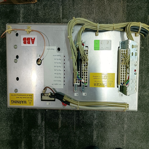
Home > Product > Gas turbine system > DS200SIOBH1ABA steam turbine card
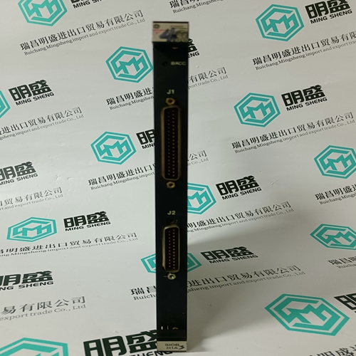
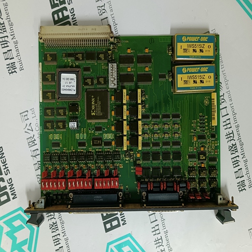
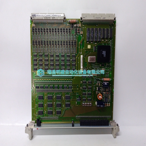
DS200SIOBH1ABA steam turbine card
- Product ID: DS200SIOBH1ABA
- Brand: GE
- Place of origin: the United States
- Goods status: new/used
- Delivery date: stock
- The quality assurance period: 365 days
- Phone/WhatsApp/WeChat:+86 15270269218
- Email:stodcdcs@gmail.com
- Tags:DS200SIOBH1ABAsteam turbine card
- Get the latest price:Click to consult
The main products
Spare parts spare parts, the DCS control system of PLC system and the robot system spare parts,
Brand advantage: Allen Bradley, BentlyNevada, ABB, Emerson Ovation, Honeywell DCS, Rockwell ICS Triplex, FOXBORO, Schneider PLC, GE Fanuc, Motorola, HIMA, TRICONEX, Prosoft etc. Various kinds of imported industrial parts
DS200SIOBH1ABA steam turbine card
If fuses are used to secure the power supply, then semi-conductor fuses are not required. gL classification fuses will suffice. Fuses should be selected as per the mains current. 4.4. Mains contactor The following contactor choices apply to the direct connection of the KDV to 3 x 380V ... 460V AC mains, as per the connection diagram. The mains current should guide the choice. Starting current peaks do not have to be taken into consideration because the KDV 4.1’s charging current limit with link circuit power is equal to or greater than 10kW.Additional capacitors Additional capacitors CZ 1.02 or additional capacitors module TCM can be connected to the d.c. voltage link circuit to heighten the performance of the KDV 4.1. An additional capacitor with 4mF is needed to implement maximum equipment power (see Section 2.1). It is necessary, in some cases, for drives to run free after a power failure. Energy stored in the link circuit can be used for this purpose. Additional capacitors can increase the energy stored in the link circuit. A maximum of 8mF additional capacitors can be connected. 4.8. Fault current safety devices Do not install an residual current operated device in the KDV 4’s mains lead (as per VDE 0160, Section 6.5). 4.9. Minimum clearance to flammable materials The bleeder resistor is set in a separate cabinet within the KDV 4. Such flammable materials as lines and cables must maintain a minimum clearance of 100 mm upwards and 40 mm sidewards and forwards.
Mains supply earthing requirements
The KDV 4 can be connected to earthed, threephase mains supplies without the need for potential isolation. On non-earthed threephase mains supplies (IT mains), the phase-to-phase voltage is present during an earth fault between the case and the power connection of the KDV 4. The KDV 4 can be protected against overvoltages if • the KDV 4 is connected via a transformer, and • if the machine is protected by overvoltage conductors. Connecting the KDV 4 via an isolation transformer offers the best protection against overvoltage and the greatest degree of operating safety. Grounded threephase mains Ungrounded threephase mains • Periodic overvoltages at the KDV 4 between the phase conductor (1U1, 1V1, 1W1, 2U1, 2V1, 2W1) and the housing should not be permitted to exceed 1000V (peak value). • Non-periodic overvoltages, as per VDE 0160, between the phase conductor and the housing are permissible for the KDV 4 in terms of the following diagram.
Signal voltage Signal voltages can be tapped from terminal strip X10. These terminals are there for measuring and testing purposes. If these voltages are used outside the KDV 4.1, then attention must be paid that no disruptive voltages are coupled in (short, shielded lines).
