Home > Product > PLC programmable module > RELIANCE DSA-MTR-60D Logic operation module
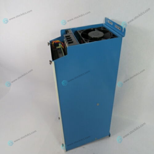
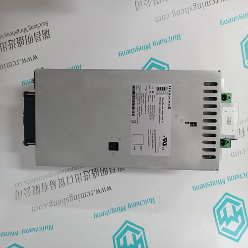
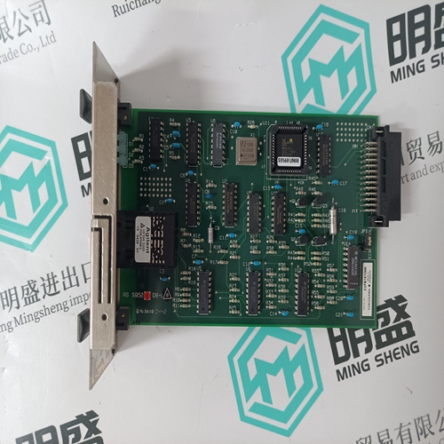
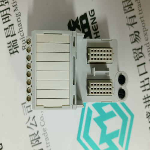
RELIANCE DSA-MTR-60D Logic operation module
- Product ID: DSA-MTR-60D
- Brand: Reliance
- Place of origin: The United States
- Goods status: new/used
- Delivery date: stock
- The quality assurance period: 365 days
- Phone/WhatsApp/WeChat:+86 15270269218
- Email:stodcdcs@gmail.com
- Tags:RELIANCEDSA-MTR-60DLogic operation module
- Get the latest price:Click to consult
RELIANCE DSA-MTR-60D Logic operation module
The MVME177 was tested in an FCC-compliant chassis, and meets the requirements for Class A equipment. FCC compliance was achieved under the following conditions: 1. Shielded cables on all external I/O ports. 2. Cable shields connected to earth ground via metal shell connectors bonded to a conductive module front panel. 3. Conductive chassis rails connected to earth ground. This provides the path for connecting shields to earth ground. 4. Front panel screws properly tightened. For minimum RF emissions, it is essential that the conditions above be implemented; failure to do so could compromise the FCC compliance of the equipment containing the module.
General Description
The MVME177 is a double-high VMEmodule based on the MC68060 microprocessor. The MVME177 has:
❏ 4/8/16/32/64/128/256 MB of ECC-protected DRAM
❏ 8KB of static RAM and time of day clock (with battery backup)
❏ Ethernet transceiver interface
❏ Four serial ports with EIA-232-D interface
❏ Four tick timers
❏ Watchdog timer
❏ 4 MB of Flash memory ❏ Two EPROM sockets ❏ SCSI bus interface with DMA The I/O on the MVME177 is connected to the VMEbus P2 connector. The main board is connected through a P2 transition board and cables to the transition boards.
The MVME712x transition boards
provide configuration headers and industry standard connectors for the I/O devices. The VMEbus interface is provided by an ASIC called the VMEchip2. The VMEchip2 includes: ❏ Two tick timers
❏ A watchdog timer
❏ Programmable map decoders for the master and slave interfaces ❏ VMEbus to/from local bus DMA controller
❏ VMEbus to/from local bus non-DMA programmed access interface


Professional seller
Professional sales of major electrical brand products in the world
Overseas direct purchase of products, authentic inventory, price concessions
After sales warranty, complete models, same products, different prices and services
