Home > Product > PLC programmable module > RELIANCE S-D4008-E Analog control module
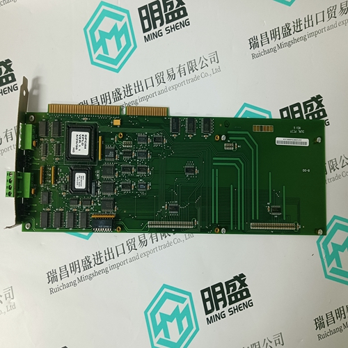
RELIANCE S-D4008-E Analog control module
- Product ID: S-D4008-E
- Brand: Reliance
- Place of origin: The United States
- Goods status: new/used
- Delivery date: stock
- The quality assurance period: 365 days
- Phone/WhatsApp/WeChat:+86 15270269218
- Email:xiamen2018@foxmail.com
- Tags:RELIANCES-D4008-EAnalog control module
- Get the latest price:Click to consult
RELIANCE S-D4008-E Analog control module
If the shipping carton is damaged upon receipt, request carrier's agent be present during unpacking and inspection of equipment Unpack equipment from shipping carton. Refer to packing list and verify that all items are present. Save packing material for storing and reshipping of equipment.The following list identifies the things you will need to do before you can use this board, and where to find the information you need to perform each step. Be sure to read this entire chapter and read all Caution notes before beginning.Set jumpers on the transition board; connect and install the transition board, P2 adapter module, and optional SCSI device cables.
Hardware Preparation
To select the desired configuration and ensure proper operation of the MVME177, certain option modifications may be necessary before installation. The MVME177 provides software control for most of these options. Some options cannot be done in software, so are done by jumpers on headers. Most other modifications are done by setting bits in control registers after the MVME177 has been installed in a system. (The MVME177 registers are described in Chapter 4, and/or in the Single Board Computers Programmer's Reference Guide as listed in Related Documentation in Chapter 1).
The location of switches, jumper headers
connectors, and LED indicators on the MVME177 is illustrated in Figure 2-1. The MVME177 has been factory tested and is shipped with the factory jumper settings described in the following sections. The MVME177 operates with its required and factory-installed Debug Monitor, MVME177Bug (177Bug), with these factory jumper settings. Settings can be made for: ❏ General purpose readable jumpers on header (J1) ❏ SRAM backup power source select header (J2) (optional) ❏ System controller header (J6) ❏ Thermal sensing pins (J7) ❏ EPROM/Flash configuration jumper (J8) ❏ Serial port 4 clock configuration select headers (J9 and J10) Refer to Table 2-2 to configure the jumper settings for each header.

Professional seller
Professional sales of major electrical brand products in the world
Overseas direct purchase of products, authentic inventory, price concessions
After sales warranty, complete models, same products, different prices and services