Home > Product > PLC programmable module > RELIANCE UGZ3455 Data transmission module
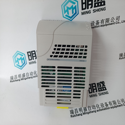
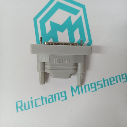
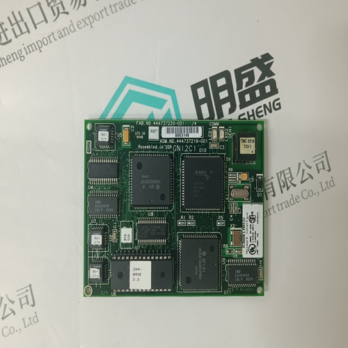
RELIANCE UGZ3455 Data transmission module
- Product ID: UGZ3455
- Brand: Reliance
- Place of origin: The United States
- Goods status: new/used
- Delivery date: stock
- The quality assurance period: 365 days
- Phone/WhatsApp/WeChat:+86 15270269218
- Email:xiamen2018@foxmail.com
- Tags:RELIANCEUGZ3455Data transmission module
- Get the latest price:Click to consult
RELIANCE UGZ3455 Data transmission module
The MVME177 may be configured with these readable jumpers. These jumpers can be read as a register (at $FFF40088) in the VMEchip2 LCSR. The bit values are read as a one when the jumper is off, and as a zero when the jumper is on. This jumper block (header J1) contains eight bits. Refer to the Single Board Computers Programmer's Reference Guide. The MVME177Bug reserves/defines the four lower order bits (GPI3 to GPI0). The following table shows the bits reserved/defined by the debugger:When this bit is a one (high), it instructs the debugger to use local Static RAM for its work page (i.e., variables, stack, vector tables, etc.).When this bit is a one (high), it instructs the debugger to use the default setup/operation parameters in ROM versus the user setup/operation parameters in NVRAM. This is the same as depressing the RESET and ABORT switches at the same time. This feature can be used in the event the user setup is corrupted or does not meet a sanity check. Refer to the ENV command (Appendix B) for the ROM defaults.
Be sure that the two 256K x 16 177Bug
EPROMs are installed in proper sockets on the MVME177 module. Install the odd label (such as B01) EPROM in socket XU1 (for Least Significant Words), and install the even label (such as B02) EPROM in XU2 (for Most Significant Words). Be sure that physical chip orientation is correct, with flatted corner of each EPROM aligned with corresponding portion of EPROM socket on the MVME177 module. 4. This completes the MVME177 Module hardware preparation procedures. Proceed to the next section to install the module in the chassis. Refer to the setup procedure for your particular chassis or system for details concerning the installation of the MVME177.
MVME177 Module Installation Instructions
When you have configured the MVME177’s headers and installed the selected EPROMs in the sockets as described previously, install the MVME177 module in the system as follows: 1. Turn all equipment power OFF and disconnect the power cable from the AC power source. ! Caution Inserting or removing modules while power is applied could result in damage to module components. ! Warning Dangerous voltages, capable of causing death, are present in this equipment. Use extreme caution when handling, testing, and adjusting.


Professional seller
Professional sales of major electrical brand products in the world
Overseas direct purchase of products, authentic inventory, price concessions
After sales warranty, complete models, same products, different prices and services
