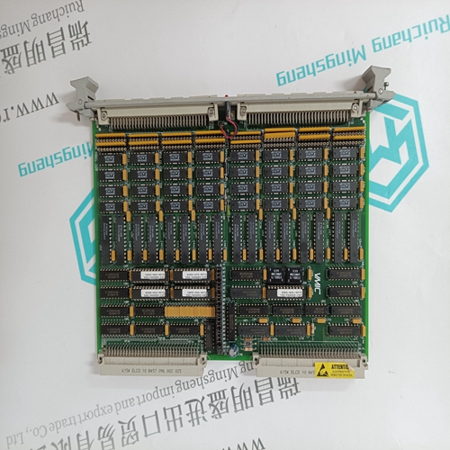
Home > Product > PLC programmable module > 531X307LTBAJG1 A combustion engine card
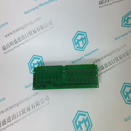
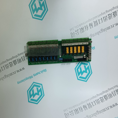
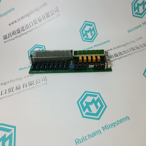
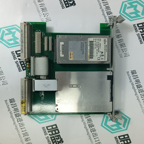
531X307LTBAJG1 A combustion engine card
- Product ID: 531X307LTBAJG1
- Brand: GE
- Place of origin: the United States
- Goods status: new/used
- Delivery date: stock
- The quality assurance period: 365 days
- Phone/WhatsApp/WeChat:+86 15270269218
- Email:stodcdcs@gmail.com
- Tags:531X307LTBAJG1A combustion engine card
- Get the latest price:Click to consult
The main products
Spare parts spare parts, the DCS control system of PLC system and the robot system spare parts,
Brand advantage: Allen Bradley, BentlyNevada, ABB, Emerson Ovation, Honeywell DCS, Rockwell ICS Triplex, FOXBORO, Schneider PLC, GE Fanuc, Motorola, HIMA, TRICONEX, Prosoft etc. Various kinds of imported industrial parts
531X307LTBAJG1 A combustion engine card
10.2 SYSTEM CHECKOUT 1. Check that the correct circuit boards are installed and fully seated in the case as follows. The controller model number on the P&I drawing should match the model number on the controller’s case. Compare the model number to the Model Designation table in Section 14 to be sure the proper boards are installed. NOTE When power is applied to the controller, an installed hardware list can be viewed in the STATN function block. Refer to Section 3.1.2 for board description and ID. 2. Check all wiring between the controller and external equipment (e.g. transmitters, recorders, power supplies). Check for correct and secure connections, correct wire gauge and insulation, adequate support (ties, raceways, conduit), and protection from damage (sharp edges, moving equipment, chemicals, abrasion). 3. Test all equipment connected to the controller for proper operation. Refer to the equipment manufacturer’s literature as necessary. 4. Apply power to the controller and note the faceplate displays during power up. See Section 10.1.1 for a description of the faceplate displays during power up. 5. Based on the controller hardware present, the current configuration in the controller, and the external equipment, exercise the system in a systematic manner to ensure proper operation.
11.0 MAINTENANCE
Controller maintenance requirements are minimal. Activities such as cleaning and visual inspections should be performed at regular intervals. The severity of the controller’s operating environment will determine the frequency of maintenance. Additional topics including troubleshooting, assembly replacement, and software compatibility are also covered. Figure 11-1 has an exploded view of the controller. Before servicing or calibration the equipment, note the following statements. • Maintenance should be performed only by qualified personnel. Failure to properly maintain the equipment can result in death, serious injury, or product failure. This manual should be carefully reviewed, understood, and followed. • The steps in the Preventive Maintenance section should be performed regularly. • The procedures in this section do not represent an exhaustive survey of maintenance steps necessary to ensure safe operation of the equipment. Particular applications may require further procedures. Should further information be desired or should particular problems arise which are not covered sufficiently for the purchaser’s purposes, the matter should be referred to the local Siemens sales office. • The use of unauthorized parts in the repair of the equipment or tampering by unqualified personnel will result in dangerous conditions that can cause death, serious injury, or equipment damage. Follow all safety instructions contained herein.
