Home > Product > Robot control system > Okuma E4809-436-115-A Input interface module
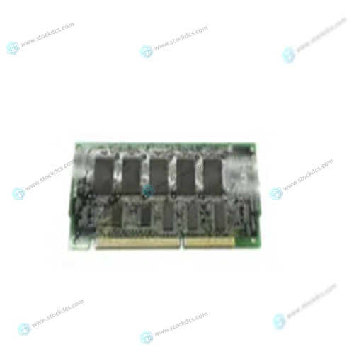
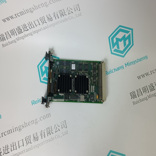
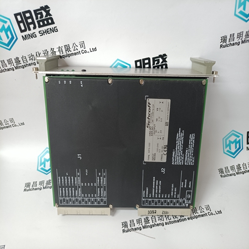
Okuma E4809-436-115-A Input interface module
- Product ID: E4809-436-115-A
- Brand: OKUMA
- Place of origin: The United States
- Goods status: new/used
- Delivery date: stock
- The quality assurance period: 365 days
- Phone/WhatsApp/WeChat:+86 15270269218
- Email:stodcdcs@gmail.com
- Tags:OkumaE4809-436-115-AInput interface module
- Get the latest price:Click to consult
Okuma E4809-436-115-A Input interface module
This register will allow the VMEbus address and the local address to be different. The value in this register is the base address of local resource that is associated with the starting and ending address selection from the previous questions. Default is 0 This register defines which bits of the address are significant. A logical one "1" indicates significant address bits, logical zero "0" is non-significant. Default is 0 Defines the access restriction for the address space defined with this slave address decoder. Default is $01FF.Base address of the VMEbus resource that is accessible from the local bus. Default is the end of calculated local memory.Ending address of the VMEbus resource that is accessible from the local bus. Default is the end of calculated memory.
Network Controller Modules Supported
The VMEbus network controller modules in the following table are supported by 177Bug. The default address for each type and position is shown to indicate where the controller must reside to be supported by 177Bug. The controllers are accessed via the specified CLUN and DLUNs listed here. The CLUN and DLUNs are used in conjunction with the debugger commands: ❏ NBH
❏ Try these simple troubleshooting steps before calling for help or sending your CPU board back for repair.
❏ Some of the procedures will return the board to the factory debugger environment. (The board was tested under these conditions before it left the factory.)
❏ Selftest may not run in all user-customized environments.
Basic Troubleshooting Steps
1. Make sure the system is plugged in. 2. Check that the board is securely installed in its backplane or chassis. 3. Check that all necessary cables are connected to the board, per this manual. 4. Check for compliance with System Considerations, per this manual. 5. Review the Installation and Startup procedures, per this manual. In most cases, this includes a step-by-step powerup routine. Try it. B. If the LEDs are lit, the board may be in the wrong slot. 1. For VMEmodules, the CPU board should be in the first (leftmost) slot. 2. Also check that the “system controller” function on the board is enabled, per this manual. C.The “system console” terminal may be configured wrong. Configure the system console terminal per this manual.

Payment method and delivery
Shipment: EMS,DHL,UPS & FEDEX
Payment: T/T or Western Union
Professional seller
Professional sales of major electrical brand products in the world
Overseas direct purchase of products, authentic inventory, price concessions
After sales warranty, complete models, same products, different prices and services