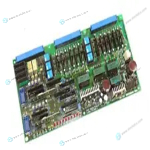
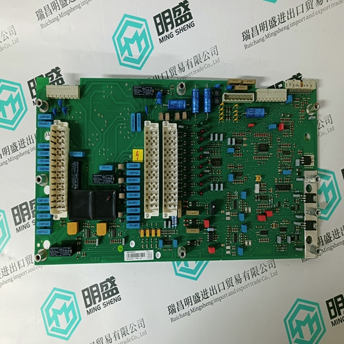
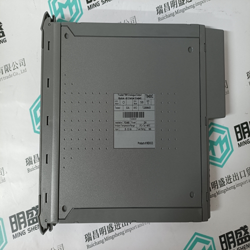
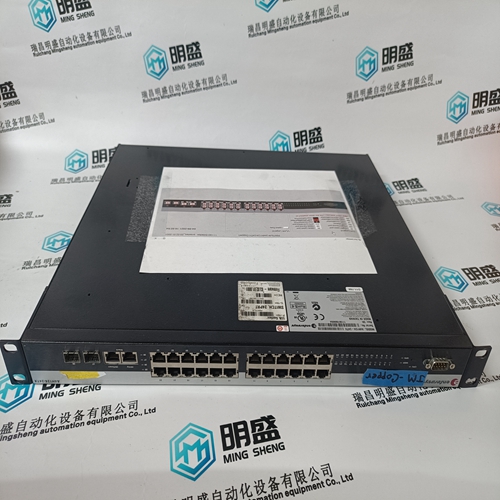
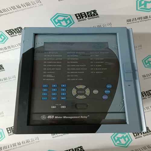
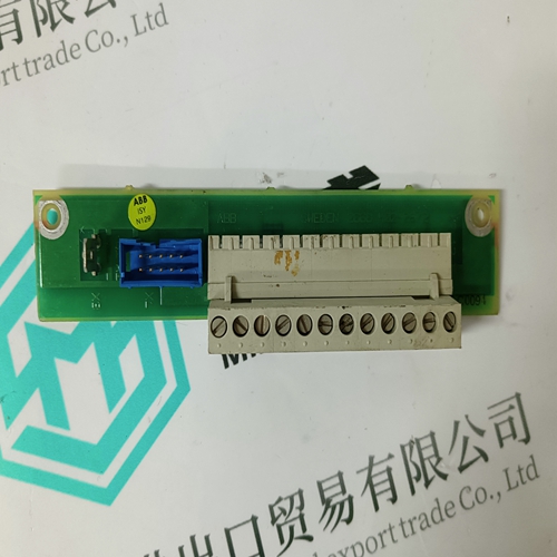
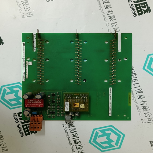
Home > Product > Robot control system > Okuma E4809-770-065-A Network communication card
Okuma E4809-770-065-A Network communication card
- Product ID: E4809-770-065-A
- Brand: OKUMA
- Place of origin: The United States
- Goods status: new/used
- Delivery date: stock
- The quality assurance period: 365 days
- Phone/WhatsApp/WeChat:+86 15270269218
- Email:stodcdcs@gmail.com
- Tags:OkumaE4809-770-065-ANetwork communication card
- Get the latest price:Click to consult
Okuma E4809-770-065-A Network communication card
Disconnect all power from your system. 2. Check that the proper debugger EPROM or debugger Flash memory is installed per this manual. 3. Reconnect power. 4. Restart the system by “double-button reset”: press the RESET and ABORT switches at the same time; release RESET first, wait seven seconds, then release ABORT. 5. If the debug prompt appears, go to step IV or step V, as indicated. If the debug prompt does not appear, go to step VI.6.You may need to use the cnfg command (see your board Debugger Manual) to change clock speed and/or Ethernet Address, and then later return to The tests take as much as 10 minutes, depending on RAM size. They are complete when the prompt returns. (The onboard selftest is a valuable tool in isolating defects.) 8. The system may indicate that it has passed all the selftests. Or, it may indicate a test that failed. If neither happens, enter
Related Documentation
The MVME187 ships with a start-up installation guide
(MVME187IG/D, the document you are presently reading) which
includes installation instructions, jumper configuration
information, memory maps, debugger/monitor commands, and
any other information needed for start-up of the board.
If you wish to develop your own applications or need more detailed
information about your MVME187 Single Board Computer, you
may purchase the additional documentation (listed on the
following pages) through your local Motorola sales office.
If any supplements have been issued for a manual or guide, they
will be furnished along with the particular document. Each
Motorola Computer Group manual publication number is suffixed
with characters which represent the revision level of the document,
such as “/D2” (the second revision of a manual); a supplement
bears the same number as a manual but has a suffix such as
“/D2A1” (the first supplement to the second edition of the
manual)
Other Applicable Motorola Publications
The following publications are applicable to the MVME187 and may provide additional helpful information. They may be purchased through your local Motorola sales office.MVME187 RISC Single Board Computer Support Information The SIMVME187 manual contains the connector interconnect signal information, parts lists, and the schematics for the MVME187.For your convenience, we have collected user's manuals for each of the peripheral controllers used on the MVME187 from the suppliers.


Payment method and delivery
Shipment: EMS,DHL,UPS & FEDEX
Payment: T/T or Western Union
Professional seller
Professional sales of major electrical brand products in the world
Overseas direct purchase of products, authentic inventory, price concessions
After sales warranty, complete models, same products, different prices and services
