Home > Product > Gas turbine system > VMIVME-7666-111000350-017666-111000 C card
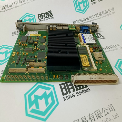
VMIVME-7666-111000350-017666-111000 C card
- Product ID: VMIVME-7666-111000350-017666-111000 C
- Brand: GE
- Place of origin: the United States
- Goods status: new/used
- Delivery date: stock
- The quality assurance period: 365 days
- Phone/WhatsApp/WeChat:+86 15270269218
- Email:stodcdcs@gmail.com
- Tags:VMIVME-7666-111000350-017666-111000 Ccard
- Get the latest price:Click to consult
The main products
Spare parts spare parts, the DCS control system of PLC system and the robot system spare parts,
Brand advantage: Allen Bradley, BentlyNevada, ABB, Emerson Ovation, Honeywell DCS, Rockwell ICS Triplex, FOXBORO, Schneider PLC, GE Fanuc, Motorola, HIMA, TRICONEX, Prosoft etc. Various kinds of imported industrial parts
VMIVME-7666-111000350-017666-111000 C card
Loop powered detectors require a two wire connection and the detector documentation will indicate the positive and negative loop connections, usually brown and blue respectively. At the System 57 end of the field cable the two detector wires should each be connected to one of either the S, 01 or NS terminals on the Field Interface or Relay Card that is attached to the required Single Channel Display Card. The two terminals used will vary depending upon whether the location of the measuring resistance is in the loop supply or return paths.
Transmitters powered from the 5701 Control Card require either three or four wire connections and the detector documentation will indicate the 0V and +24V power connections and the positive and negative loop connections. At the System 57 end of the field cable the detector wires should be connected to the S, 01, NS, 0V or 24V terminals on the Field Interface or Relay Card that is attached to the required Single Channel Display Card. The exact terminals used vary depending upon whether three or four wire topology is used, and the requirement for loop current source or sink configuration. The Schematics below detail the connections for 3 wire current sink or source transmitters. For other schematics (including isolated and barrier) refer to operating manual 05701-M-5001.
Gas Card and Catalytic Type Detector
Catalytic detectors require a three wire connection and the detector documentation will indicate three connections S, 01 and NS, which are usually brown, white and blue respectively. At the System 57 end of the field cable, the three detector wires should each be connected to the respective matching S, 01 or NS terminal of the appropriate channel on the Quad Relay Interface Card that is attached to the required Four Channel Control Card.8.6 5704 Gas Card and 2 Wire Loop Powered Detectors Loop powered detectors require a two wire connection and the documentation will indicate the positive and negative loop connections, usually brown and blue respectively. At the System 57 end of the field cable the two detector wires should be connected to the S (positive) and 01 (negative) terminals of the appropriate channel on the Quad Relay Interface Card that is attached to the required Four Channel Control Card.