Home > Product > Gas turbine system > IS215UCVGM06A IS215UCVGH1A Combustion engine general card
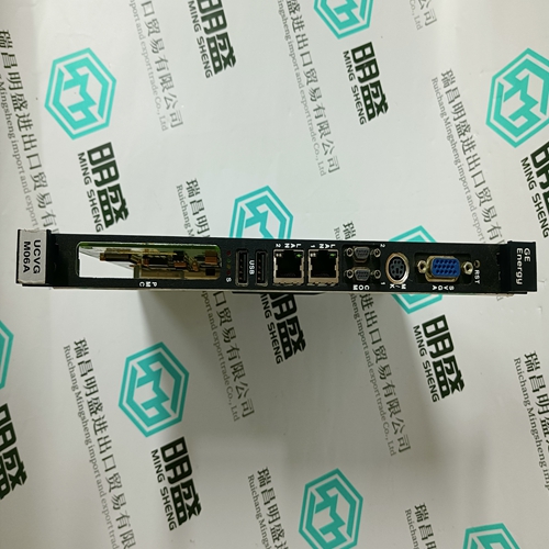
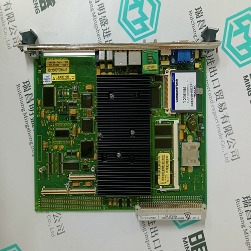
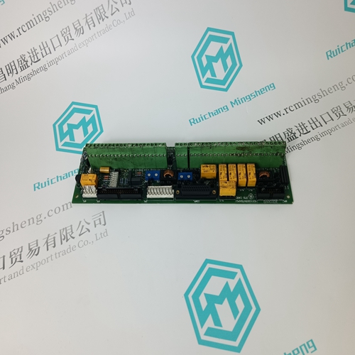
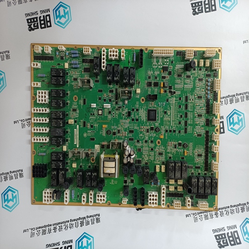
IS215UCVGM06A IS215UCVGH1A Combustion engine general card
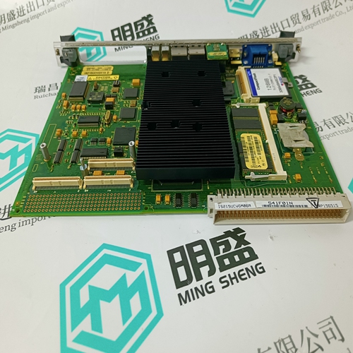
- Product ID: IS215UCVGM06A IS215UCVGH1A
- Brand: GE
- Place of origin: the United States
- Goods status: new/used
- Delivery date: stock
- The quality assurance period: 365 days
- Phone/WhatsApp/WeChat:+86 15270269218
- Email:stodcdcs@gmail.com
- Tags:IS215UCVGM06A IS215UCVGH1ACombustion engine general card
- Get the latest price:Click to consult
The main products
Spare parts spare parts, the DCS control system of PLC system and the robot system spare parts,
Brand advantage: Allen Bradley, BentlyNevada, ABB, Emerson Ovation, Honeywell DCS, Rockwell ICS Triplex, FOXBORO, Schneider PLC, GE Fanuc, Motorola, HIMA, TRICONEX, Prosoft etc. Various kinds of imported industrial parts
IS215UCVGM06A IS215UCVGH1A Combustion engine general card
Transmitters require either three or four wire connections and the dete will indicate the 0V and +24V power connections and the positive and negative loop connections. At the System 57 end of the field cable the detector loop signal wires sh connected to the S, 01, NS terminals on the Quad Relay Interface Card that is attached to the required Four Channel Control Card. The exact terminals used vary depending upon whether three or four wire topology is used, the requirement for a loop current source configuration and the channel to be connected to. The transmitter power connection +2 and 0V should be connected to a suitable dc supply.
The 5704F fire input circuit operates from the system dc input supply (21 to 32V) but has a built-in voltage limiter that limits the maximum loop voltage to +24V to protect the detectors from damage. When the system supply is less than +24V the limiter has no effect and the loop will see the true input supply voltage. The loop current is determined by measuring the voltage across a 220 ohm current sense resistance. A link selectable 330 ohm barrier equivalent resistance is incorporated for use when an external IS barrier is NOT fitted. For fault monitoring purposes, an end of line (EOL) resistor must be fitted in or after the last detector on the loop. The typical value for the end of line resistance is 5.1k ohms although this may need to be reduced when many detectors are fitted onto the loop.
Typical Loop Powered Detector Connections
Loop powered detectors (e.g. most smoke, heat and manual call points) have two wire connection. The detector documentation will indicate the positive and negative loop connections. Multiple detectors may be connected in parallel on a single loop input provided the loop operational limit for quiescent current is not exceeded. At the System 57 end of the field cables, the two detector wires should be connected to the appropriate channels IN+ and IN- terminals of the Hex Relay Interface Card that is attached to the required 5704F Control Card. The loop current always flows from the IN+ terminal and returns via the IN- terminal. For fault monitoring purposes an end of line (EOL) resistor must be fitted in or after the last detector on the loop. The typical value for end of line resistance is 5.1k ohms. The detector cable screen, or steel wire armour or braid as appropriate, should be connected to the system protective earth. This can be achieved where the cable enters the cabinet by using a metal cable gland, or by other suitable means, and avoiding any screen tails within the cabinet. Where the cable consists of a separate screen sheath and wire armour or braid, the armour should be connected at the cabinet entry to the protective earth and the screen sheath should be connected to the GROUND terminal of the Hex Relay Interface Card or to a suitable instrument earth point.