Home > Product > Servo control system > WOODWARD 5466-332 I/O bus card
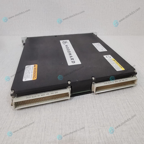
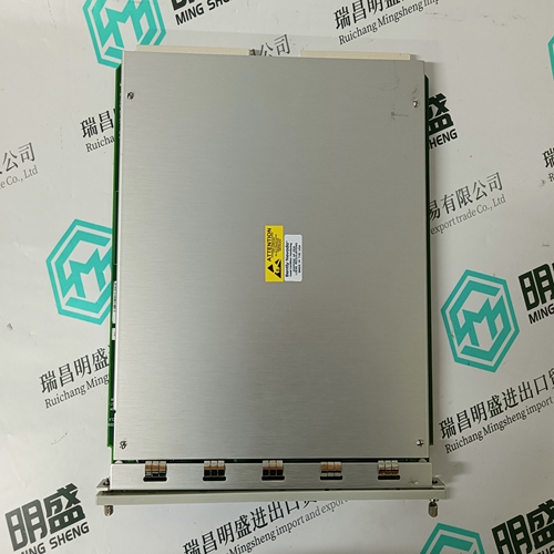
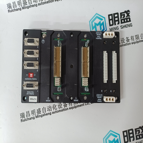
WOODWARD 5466-332 I/O bus card
- Product ID: 5466-332
- Brand: WOODWARD
- Place of origin: The United States
- Goods status: new/used
- Delivery date: stock
- The quality assurance period: 365 days
- Phone/WhatsApp/WeChat:+86 15270269218
- Email:stodcdcs@gmail.com
- Tags:WOODWARD5466-332I/O bus card
- Get the latest price:Click to consult
WOODWARD 5466-332 I/O bus card
Switch segments six through eight help determine the location of the two CSRs in the memory map. The actual decode of the CSR is determined by the settings for switch segments six through eight, the existence of a board select as determined by switch segments two through five, and address bit A2. Settings for switch segments six through eight are compared to bus address bits A31-A29. Leaving the switch segment setting open lets the lines pull high so that A31-A29 = 111 matches. This is the setting required by system software. Changing to a different switch setting is for specific users who have a conflict with that address. A2 = 0 enables the board level CSR. A2 = 1 and a write cycle cause a write to the diagnostic registers in the Am29C660 chips (U14 and U36). A read to this location starts check bit initialization. The diagnostic latches are write-only and are written concurrently. Refer to the Am29C660 data sheet listed in Chapter 1 for diagnostic latch definition. Note that the two locations of CSR for each ECC memory board require a 4MB window in the slave bus memory map.
Installation Instructions
The following sections discuss removal and installation of the HYPERmodule mezzanine module on the MVME188A module, installation of additional memory board(s) (MVME288 series) on the MVME188A, installation of the MVME188A into a VME chassis, connection of EIA-232-D terminal(s) and cable(s), and system considerations. Ensure that ROM/PROMIEPROM/EEPROM devices are installed. Factory configuration is with the EPROMs for the MVME188Bug debug monitor. For MVME188Bug version 4.4, these are B75 in socket for U21, B76 in socket for Ul, B77 in socket for U20, and B78 in socket for U2. Ensure that all switch segments and header connections are configured as desired.
Removal and Installation of HYPERmodule Mezzanine Module
The HYPERmodule on· the MVME188A is replaceable. It is possible to upgrade the MVME188A by replacing a single-processor HYPERmodule with a dual- or quad- processor HYPERmodule as follows. a. Tum all equipment power OFF and disconnect power cable from ac power source.b. Removal of the MVME188A board set from the system differs depending on the chassis your system is in. In general, proceed as follows: 1. Open the appropriate cover(s) and/or access doors in the chassis to expose the front panels of the MVME188A.Locate the screws that fasten the HYPERmodule to the MVME188A main logic board (CPU board) at the right side of the MVME188A board set. There are four screws at the front of the boards (near the front panel) and two or three at the back of the boards (near the backplane connectors).


About us
We are professional company and we are expert in this business, we have highly experienced production team, or sales team, or purchase team, we have most advanced production line. We are reputable in the market.
Our products
A company specializes in the sales of module spare parts of global famous brands (DCS system) (robot system) (large servo control system). The company's products include distributed control system (DCS), programmable controller (PLC), MOTOROLA MVME industrial module, industrial control communication converter (Anybus), remote output/input module (RTU), industrial computer (IPC), industrial low screen screen (IPC) HMI SCSI (50, 68, 80Pin) AnyBus (Gateway) has become a global sales enterprise of industrial automation spare parts and components
