Home > Product > Servo control system > WOODWARD 5466-336 Gateway module
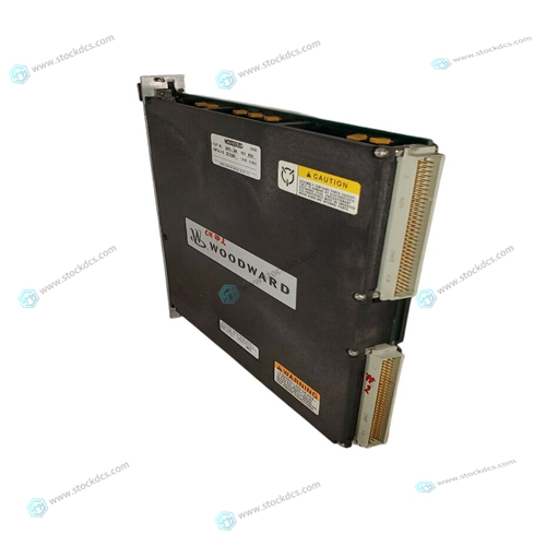
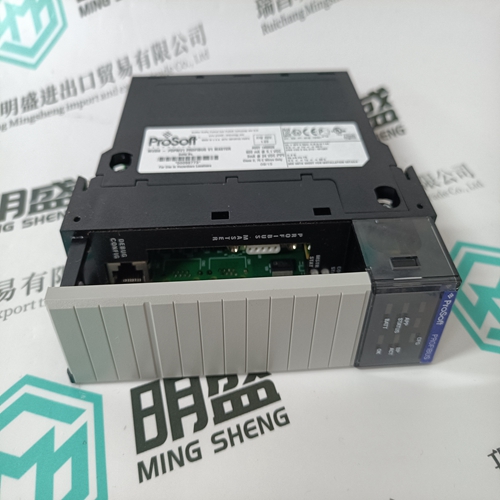
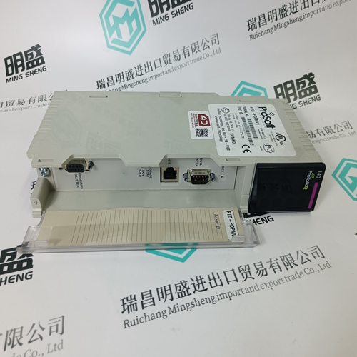
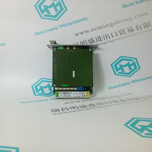
WOODWARD 5466-336 Gateway module
- Product ID: 5466-336
- Brand: WOODWARD
- Place of origin: The United States
- Goods status: new/used
- Delivery date: stock
- The quality assurance period: 365 days
- Phone/WhatsApp/WeChat:+86 15270269218
- Email:stodcdcs@gmail.com
- Tags:WOODWARD5466-336Gateway module
- Get the latest price:Click to consult
WOODWARD 5466-336 Gateway module
Carefully loosen the front and back screws, turning each screw equally one tum, then turning each one more tum, and so on until the screws and their washers are disconnected. Retain them for later use. e. Remove the HYPERmodule from the main logic board, being careful not to damage the pins of the three 100-pin connectors that connect them electrically. Do not bend the HYPERmodule board, because this could break solder connections. Lift evenly along the front edge of the HYPERmodule to uniformly separate the connector pins from their socket holes. Do not attempt to do this by hand; instead, use a stiff non-conducting board, such as a 6-inch by 6-inch by 0.25-inch epoxy-glass board. f. Install a new HYPERmodule, again being careful to mate the three 100-pin connectors exactly and evenly.Carefully connect the front and back screws and their washers, tightening each screw equally one tum, then tightening each one tum more, and so on until the screws are tight.
Installation of Additional MVME288 Series Memory Board(s)
The MVME188A can be disassembled to add up to three additional 16MB or 64MB DRAM or 32MB ECC DRAM memory boards (MVME288 series)~ Proceed as follows. a. Tum all equipment power OFF and disconnect power cable from ac power source.b. If you have not already done so, remove the MVME188A board set from the system. Removal of the MVME188A board set from the system differs depending on the chassis your system is in. In general, proceed as follows: 2-20 1. Open the appropriate cover(s) and/or access doors in the chassis to expose the front panels of the MVME188A.Unscrew (loosen) all top and bottom captive screws on the front panels of the MVME188A board set. These screws mount the MVME188A in the chassis.
Lift the top and bottom ejector handles
and pull the MVME188A board set evenly forward out of its backplane slots. c. With the board set in a vertical position, push the CPU nameplate, which is on the top right ejector handle, out of the ejector handle. Push the Motorola Logo nameplate, which is on the bottom right ejector handle, out of the ejector handle. The two steel pins are now visible through the ejector handles. Retain both nameplates for later installation. d. Using long-nose pliers, push (from the left) and pull (to the right) both steel pins until they are out of all the ejector handles. Retain these pins for possible further use. Note that if additional memory boards are installed, longer pins are required, and the original pins can not be used.The boards in the MVME188A board set are properly arranged as: leftmost, the SYSCON board; next the MEMORY board(s); and rightmost, the CPU board (with HYPERmodule). To separate the board set and/or remove memory board(s), gently pull the front panels of the boards apart and carefully separate the two 96-pin connectors P3 and P4 that are behind the front panels. Now pull the boards further apart until the compliant plugs and spacers at the two back comers of the boards pop apart.


About us
We are professional company and we are expert in this business, we have highly experienced production team, or sales team, or purchase team, we have most advanced production line. We are reputable in the market.
Our products
A company specializes in the sales of module spare parts of global famous brands (DCS system) (robot system) (large servo control system). The company's products include distributed control system (DCS), programmable controller (PLC), MOTOROLA MVME industrial module, industrial control communication converter (Anybus), remote output/input module (RTU), industrial computer (IPC), industrial low screen screen (IPC) HMI SCSI (50, 68, 80Pin) AnyBus (Gateway) has become a global sales enterprise of industrial automation spare parts and components
