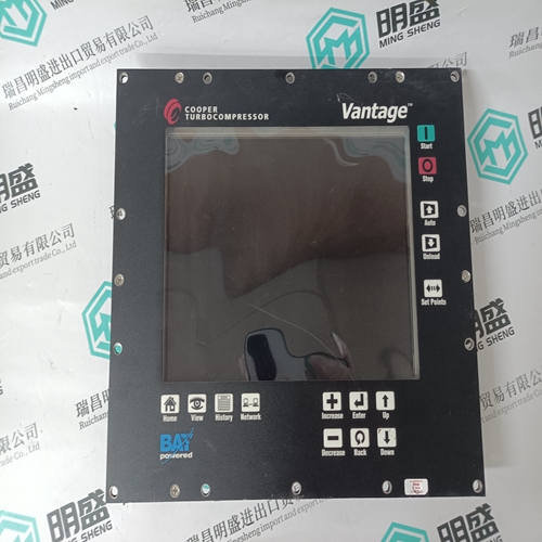
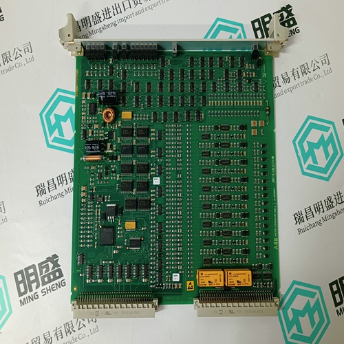
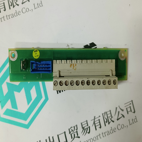
Home > Product > Servo control system > WOODWARD 5466-348 Logic sequence module
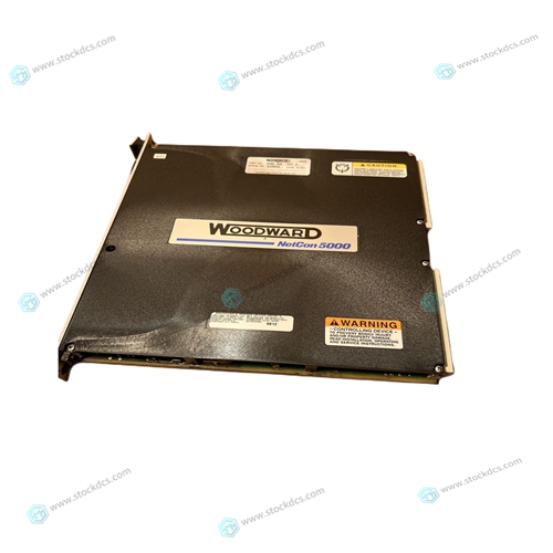
WOODWARD 5466-348 Logic sequence module
- Product ID: 5466-348
- Brand: WOODWARD
- Place of origin: The United States
- Goods status: new/used
- Delivery date: stock
- The quality assurance period: 365 days
- Phone/WhatsApp/WeChat:+86 15270269218
- Email:stodcdcs@gmail.com
- Tags:WOODWARD5466-348Logic sequence module
- Get the latest price:Click to consult
WOODWARD 5466-348 Logic sequence module
Remove the filler panels from the appropriate card slots at the front and rear of the chassis (if the chassis has a rear card cage). The MVME188A is to be installed in the front of the chassis and the MVME714M (if required) may be installed in the front or the rear of the chassis. The MVME188A module requires power from both Pl and P2 for all of its boards (system controller, memory, and main logic with HYPERmodule mezzanine). It may be installed in any three or more adjacent double-height unused card slots, if it is not configured as system controller. (If the MVME188A has had extra memory boards added, it may take 4, 5, or 6 slots.) If the MVME188A is configured as system controller, it must be installed in the left-most three card slots (slots 1, 2, and 3) to correctly initiate the bus-grant daisy-chain and to have proper operation of the !ACK-daisy-chain driver.
Remove IACK and BG jumpers
from header on chassis backplane for the first card slot the MVME188A is instaHed in. (The memory board(s) and the main logic board (CPU board) use the succeeding card slots and have their IACK pins wired together and each pair of their BG pins wired together. Therefore, the header jumpers on these card slots can be present or absent. Refer to the MVME188A VMEmodule RISC Microcomputer Support Infonnation document listed in the Related Documentation section in Chapter 1. e. If there is a blank slot immediately to the right of the MVME188A board set you are ready to install, locate the corresponding slot on the backplane. Install five jumpers across the following pairs of lines for this slot. These connect the Bus Grant (BG) and Interrupt Acknowledge (IACK) daisy-chain signals across this slot.
If you installed jumpers at a slot in the previous step
place a one-slot wide filler panel in this slot and secure it by tightening its captive screws. Make good contact with the transverse mounting rails to minimize RFI emission. NOTE No adjustment or jumpering of the new MVME188A board set is required. g. Carefully slide the MVME188A module into the card slots by aligning the PWBs in both the top and bottom card guides. Be sure all the boards are seated properly into the Pl and P2 connectors on the backplane. Do not damage or bend connector pins. Fasten modules in chassis with the front panel captive screws provided, making good contact with the transverse mounting rails to minimize RFI emissions.


About us
We are professional company and we are expert in this business, we have highly experienced production team, or sales team, or purchase team, we have most advanced production line. We are reputable in the market.
Our products
A company specializes in the sales of module spare parts of global famous brands (DCS system) (robot system) (large servo control system). The company's products include distributed control system (DCS), programmable controller (PLC), MOTOROLA MVME industrial module, industrial control communication converter (Anybus), remote output/input module (RTU), industrial computer (IPC), industrial low screen screen (IPC) HMI SCSI (50, 68, 80Pin) AnyBus (Gateway) has become a global sales enterprise of industrial automation spare parts and components
