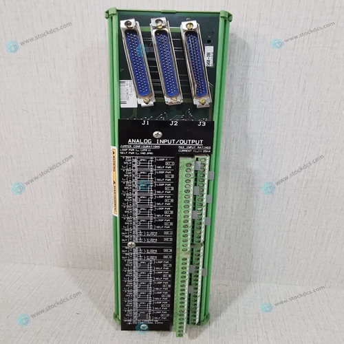
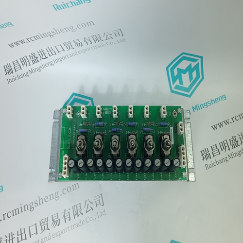
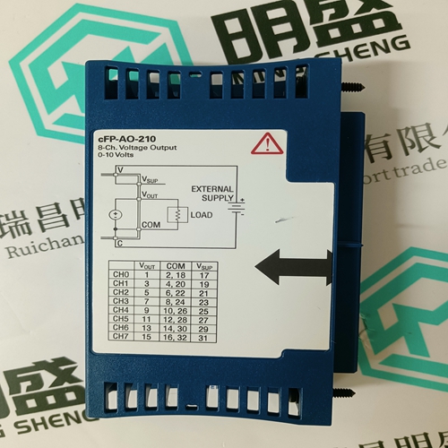
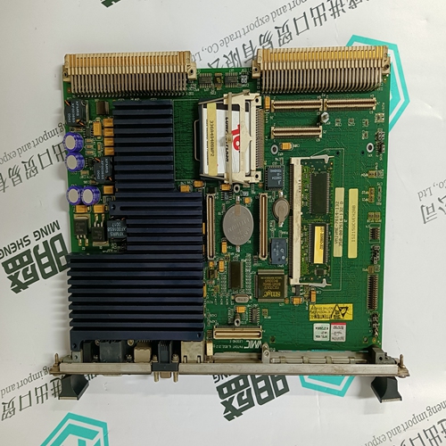
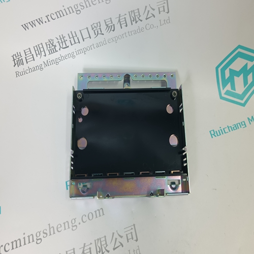
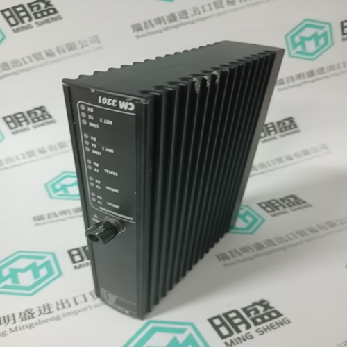
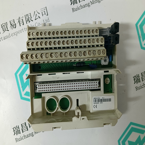
Home > Product > Servo control system > WOODWARD 5501-341 Actuator control module
WOODWARD 5501-341 Actuator control module
- Product ID: 5501-341
- Brand: WOODWARD
- Place of origin: The United States
- Goods status: new/used
- Delivery date: stock
- The quality assurance period: 365 days
- Phone/WhatsApp/WeChat:+86 15270269218
- Email:stodcdcs@gmail.com
- Tags:WOODWARD5501-341Actuator control module
- Get the latest price:Click to consult
WOODWARD 5501-341 Actuator control module
The following sections describe in detail the system controller board registers and their functions, as well as the state of all bits at power-up time (SRST) or after a local reset (LRST). All registers (with the exception of the GCSR) are located on 4-byte boundaries. Accesses to all of these registers should be 32-bit operations. All accesses to the GCSR should be 8-bit or 16-bit operations. Unless otherwise noted in the register bit descriptions, all undefined bits will be read as "1". Undefined bits are ignored on writes. All of the following registers reside on the system controller board; some are contained within LSI parts (such as the 68692 DUART). Registers that are described in an LSI data sheet are not further described here, unless their functions are defined by external hardware (such as which DUART pins connect to RTS, CTS, etc). Please refer to the data sheets of the 68692 DUART, Z8536 CIO, and MK48T02 clock for specific operation of these parts.
68692 DUART Registers
The DUART register bit assignments are described in the 68692 data sheet. How the hardware connection is made to each of the EIA-232-D serial ports on the MVME188A front panel is shown in Table 4-1. This table provides all of the required information to properly initialize and use the two serial ports. Given the clock rate of the DUART {3.6864 MHz), a square wave can be produced with anywhere from 540 nsec to 563 msec period. In lx clock mode, the range is 542 nsec to 35.5 msec in 542 nsec increments. In 16x clock mode, the range is 8.6 µ.sec to 568 msec in 8.6 µ.sec increments. All these times are approximate; actual values can be calculated from the formula in the DUART data sheet.
Z8536 CIO Registers
The CIO register bit assignments are described in the Z8536 data sheet. What hardware connection is made to each of the CIO pins that are used is shown in Table 4-2. This table provides required data to properly initialize and use the three.CIO timers. The clock rate of the 00 is 4 MHz; a square wave can be produced with anywhere from 1 µs to 4295 s (71 min.) period. Using only one timer, the range is 1 µs to 65.5 ms in 1 µs increments. By using two cascaded timers, the range can be increased a factor of 65536. This yields a minimum period of 1 µs, and a maximum period of 4295 s (in 1 µs increments). All these times are approximate; actual values can be calculated from the count values loaded into 00 registers based on a PCLK of 4 MHz (250 ns period).


About us
We are professional company and we are expert in this business, we have highly experienced production team, or sales team, or purchase team, we have most advanced production line. We are reputable in the market.
Our products
A company specializes in the sales of module spare parts of global famous brands (DCS system) (robot system) (large servo control system). The company's products include distributed control system (DCS), programmable controller (PLC), MOTOROLA MVME industrial module, industrial control communication converter (Anybus), remote output/input module (RTU), industrial computer (IPC), industrial low screen screen (IPC) HMI SCSI (50, 68, 80Pin) AnyBus (Gateway) has become a global sales enterprise of industrial automation spare parts and components
