Home > Product > Servo control system > HIMA B9361 Drive output module
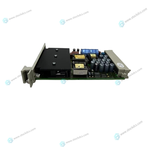
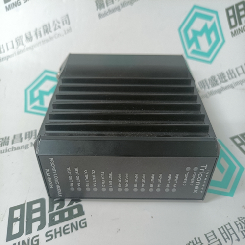
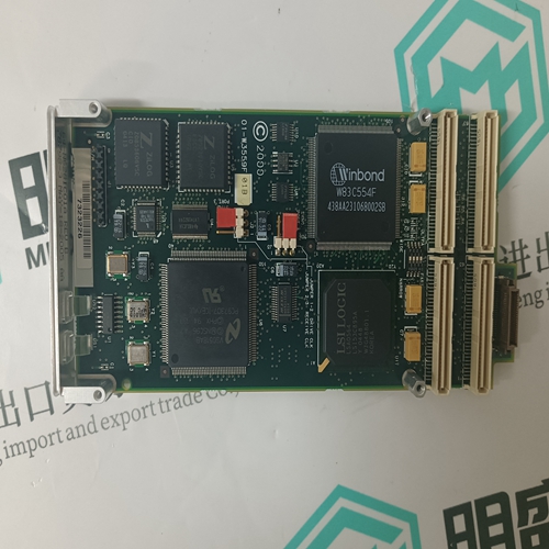
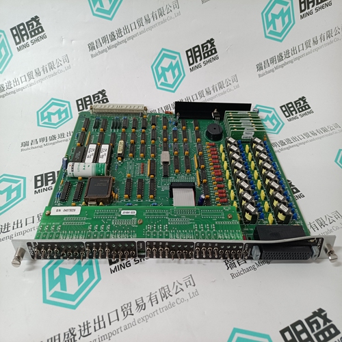
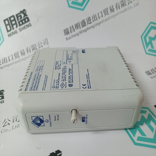
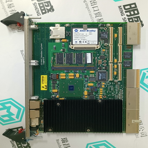
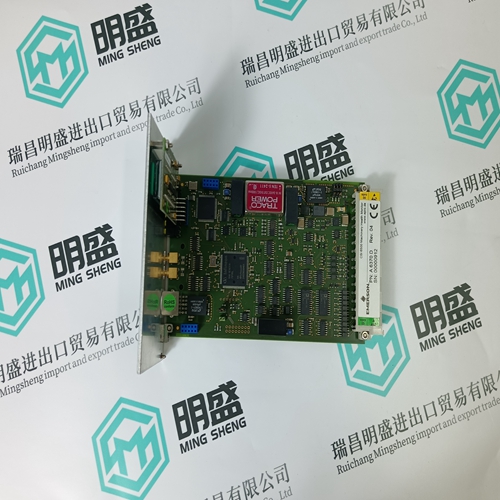
HIMA B9361 Drive output module
- Product ID: B9361
- Brand: HIMA
- Place of origin: Germany
- Goods status: new/used
- Delivery date: stock
- The quality assurance period: 365 days
- Phone/WhatsApp/WeChat:+86 15270269218
- Email:xiamen2018@foxmail.com
- Tags:HIMAB9361Drive output module
- Get the latest price:Click to consult
HIMA B9361 Drive output module
The GCSRs are a block of eight 1-byte registers located non-coterminously on consecutive 2-byte boundaries which appear both in the M bus and the VMEbus A16 (short 1/0) address spaces. All eight are intended to function identically to the corresponding GCSR registers in the Motorola MVME6000 VMEbus Interface chip (also called the VMEchip).The purpose of the MVME188A GCSR is to facilitate operation in a multi-CPU environment by allowing other CPUs on the VMEbus to interrupt, disable, communicate with, and determine the operational status of the RISC processor(s) local to the GCSR. One register of the set includes four bits which function as location monitors to allow one MVME188A processor to broadcast a signal to other MVME188A processors, if any. All eight registers are accessible from any local processor as well as from the VMEbus. Some of the bits can be individually set or cleared. Some of the bits have restricted access on either M bus or VMEbus A16 space. Bit assignments are shown in Table 4-11. Other than the location monitors, these registers are the only VMEbus A16 resource on the MVME188A.
The GCSR appears as eight one-byte
registers addressed on 2-byte boundaries in both the M bus and VMEbus A16 space. Note that this is different from all of the other MVME188A registers, which appear on 4-byte boundaries. If a 32-bit access is attempted from the VMEbus, the MVME188A does not respond; I\Ormally this cycle is terminated by a bus error from the VMEbus time-out timer. If a 4-byte access is attempted from M bus, no error is generated. However, the data returned will be two copies of the register whose 2-byte address appears on the M bus (i.e., the lower of the two addressed registers). To guarantee proper operation of the location monitors, LMO"" through LM3* should be set high by writing to Global Register 0 in VMEbus A16 space, rather than in M bus space. This will guarantee that consecutive interrupts from the same location monitor will be properly recognized, even in the absence of any VMEbus activity
Utility Control and Status Register (UCSR)
The UCSR provides status (on read) and control (on write) of many hardware functions on the system controller (utility) board. The bits are all read/write with the exception of PWRUP*, which is writable as a 1 only. {It can only be cleared by the hardware.) Bit assignments are shown in Table 4-12.This address is compared with VMEbus or slave address bits 15 through 8 to determine where to place the GCSR in the map. It is also used to determine what addresses the location monitors respond to. It is a read-only reflection of the GRP AD switch setting.This address is compared with VMEbus or slave address bits 7 through 4 to determine where to place the GCSR in the map. It is a read-only reflection of the BDAD switch setting.


About us
We are professional company and we are expert in this business, we have highly experienced production team, or sales team, or purchase team, we have most advanced production line. We are reputable in the market.
Our products
A company specializes in the sales of module spare parts of global famous brands (DCS system) (robot system) (large servo control system). The company's products include distributed control system (DCS), programmable controller (PLC), MOTOROLA MVME industrial module, industrial control communication converter (Anybus), remote output/input module (RTU), industrial computer (IPC), industrial low screen screen (IPC) HMI SCSI (50, 68, 80Pin) AnyBus (Gateway) has become a global sales enterprise of industrial automation spare parts and components
