Home > Product > Gas turbine system > HE700GEN100C Redundant module
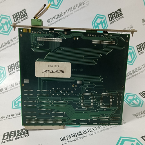
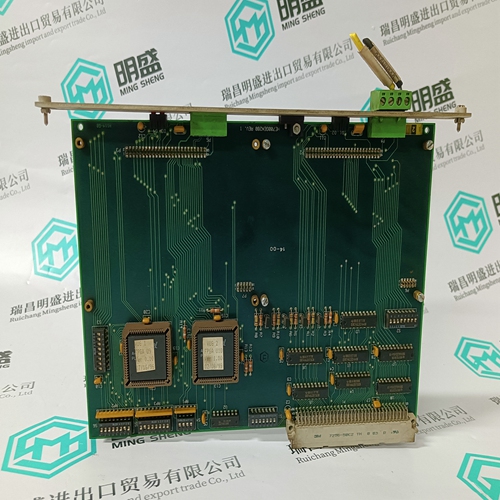
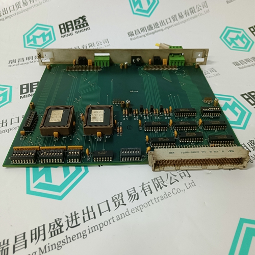
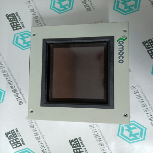
HE700GEN100C Redundant module
- Product ID: HE700GEN100C
- Brand: GE
- Place of origin: the United States
- Goods status: new/used
- Delivery date: stock
- The quality assurance period: 365 days
- Phone/WhatsApp/WeChat:+86 15270269218
- Email:stodcdcs@gmail.com
- Tags:HE700GEN100CRedundant module
- Get the latest price:Click to consult
The main products
Spare parts spare parts, the DCS control system of PLC system and the robot system spare parts,
Brand advantage: Allen Bradley, BentlyNevada, ABB, Emerson Ovation, Honeywell DCS, Rockwell ICS Triplex, FOXBORO, Schneider PLC, GE Fanuc, Motorola, HIMA, TRICONEX, Prosoft etc. Various kinds of imported industrial parts
HE700GEN100C Redundant module
Host Register Layout The card’s host registers are mapped into a separate region of PCI memory space (PCI Region 3). The base mapping address in the host system can be found by reading the PCI configuration space at offset 0x1C. The registers are stacked in memory for the 2 channels. Channel A is located in the first 8 bytes, and Channel B is located in the next 8 bytes. Refer to Section 3.2, SST-PB3-PCI-2 Configuration Space, for PCI configuration space information. Note When power is applied to the card, or after a physical reset from the system, it may take up to 2 seconds for the card to initialize. Successful initialization can be confirmed by monitoring the LEDs or by reading the HDR register, as described in Section C.1.1, Verify Card Presence.
Refer to the PCI specification and to your particular OS documentation for the function and typical uses of all other PCI configuration space registers. Note Typically, the PCI configuration space registers do not need to be written to by the host system driver. A plug and play BIOS and/or host operating system will ensure that there are no system resource conflicts.
Control Register
This bit controls and indicates whether or not the card’s processor is running. It also affects the card’s SYS LED. • When this bit is 0, the processor is halted, and the SYS LED is RED • When this bit is 1, the processor is running normally, and the LED is under processor control • When this bit is 1, and watchdog has timed out, processor is halted, and the SYS LED is RED This bit must remain low for at least 50 μs to guarantee proper reset. MemEn High (1) enables shared memory decoding of addresses in this board’s range. This board’s range is defined by the plug and play BIOS or operating system. IntEn High (1) enables interrupts on IrqLevel when a HostIrq bit is high (1). • Writing 1 enables interrupts • Writing 0 disables interrupts (the IrqPending flag still functions as described) WdTout WdTout high (‘1’) indicates that a watchdog timeout has occurred, or that the CPU has been held in RESET by some other means. To restore this bit to 0, clear CardRun. HostIrq1 This bit is used by the card processor to send interrupts to Channel B of the host. • Writing 1 acknowledges the interrupt and clears it • Writing 0 has no effect • Reading 1 indicates interrupt in progress • Reading 0 indicates interrupt complete HostIrq0 This bit is used by the card processor to send interrupts to Channel A of the host. • Writing 1 acknowledges the interrupt and clears it • Writing 0 has no effect • Reading 1 indicates interrupt in progress • Reading 0 indicates interrupt complete