Home > Product > Servo control system > HIMA F4110 Integrated circuit module
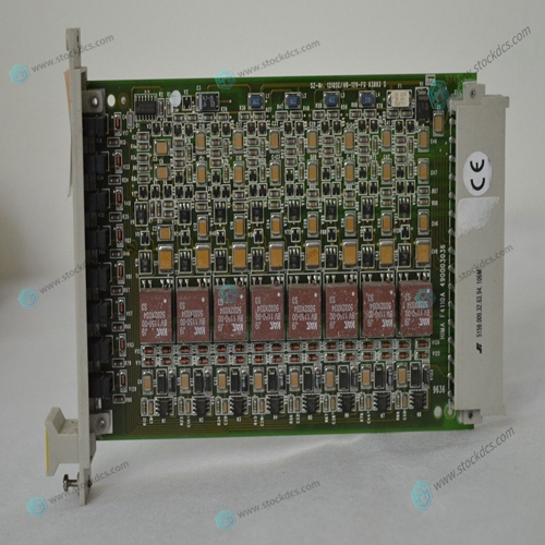
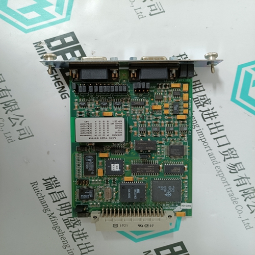
HIMA F4110 Integrated circuit module
- Product ID: F4110
- Brand: HIMA
- Place of origin: Germany
- Goods status: new/used
- Delivery date: stock
- The quality assurance period: 365 days
- Phone/WhatsApp/WeChat:+86 15270269218
- Email:xiamen2018@foxmail.com
- Tags:HIMAF4110Integrated circuit module
- Get the latest price:Click to consult
HIMA F4110 Integrated circuit module
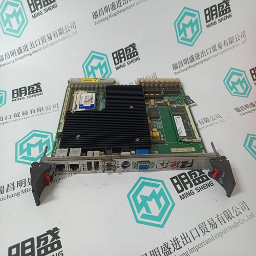
Serial port 4 can be configured to use clock signals provided by the RTXC4 and TRXC4 signal lines. Switch segments S6-1 and S6-2 on the MVME197LE configures serial port 4 to drive or receive TRXC4 and RTXC4, respectively. Factory configuration is with serial port 4 set to receive both signals (open). The remaining configuration of the clock lines is accomplished by using the Serial Port 4 Clock Configuration Select header on the MVME712M transition module. Refer to the MVME712M Transition Module and P2 Adapter Board User’s Manual for configuration of that header.The following sections discuss installation of the MVME197LE into a VME chassis, and system considerations. Ensure that BOOT ROM device is installed. Ensure that all switches are configured as desired.
MVME197LE Module Installation
Now that the MVME197LE module is ready for installation, proceed as follows: a. Turn all equipment power OFF and disconnect the power cable from the power source.b. Remove the chassis cover as instructed in the equipment user’s manual. c. Remove the filler panel(s) from the appropriate card slot(s) at the front and rear of the chassis (if the chassis has a rear card cage). The MVME197LE module requires power from both P1 and P2. It may be installed in any double-height unused card slot, if it is not configured as the system controller. If the MVME197LE is configured as the system controller, it must be installed in the left-most card slot (slot 1) to correctly initiate the bus-grant daisy-chain and to have proper operation of the IACK-daisychain driver. The MVME197LE is to be installed in the front of the chassis and the MVME712X transition board which has a double-wide front panel is to be installed in the rear of the chassis.
Carefully slide the MVME197LE module into the card slot.
Be sure the module is seated properly into the P1 and P2 connectors on the backplane. Do not damage or bend connector pins. Fasten the module in the chassis with screws provided, making good contact with the transverse mounting rails to minimize RFI emissions. e. Remove the IACK and BG jumpers from the header on the chassis backplane for the card slot in which the MVME197LE is installed. f. Connect the P2 Adapter Board and specified cable(s) to the MVME197LE at P2 on the backplane at the MVME197LE slot, to mate with (optional) terminals or other peripherals at the EIA-232-D serial ports, parallel port, SCSI ports, and LAN Ethernet port. Refer to the manuals listed in Related Documentation section for information on installing the P2 Adapter Board and the MVME712X transition module. (Some connection diagrams are provided in the MVME197LE, MVME197DP, and MVME197SP Single Board Computers Programmer’s Reference Guide). Some cable(s) are not provided with the MVME712X module and therefore, are made or provided by the user.


About us
We are professional company and we are expert in this business, we have highly experienced production team, or sales team, or purchase team, we have most advanced production line. We are reputable in the market.
Our products
A company specializes in the sales of module spare parts of global famous brands (DCS system) (robot system) (large servo control system). The company's products include distributed control system (DCS), programmable controller (PLC), MOTOROLA MVME industrial module, industrial control communication converter (Anybus), remote output/input module (RTU), industrial computer (IPC), industrial low screen screen (IPC) HMI SCSI (50, 68, 80Pin) AnyBus (Gateway) has become a global sales enterprise of industrial automation spare parts and components
