Home > Product > DCS control system > HONEYWELL 51307075-175 CC-TAIX51 module
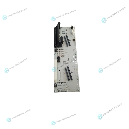
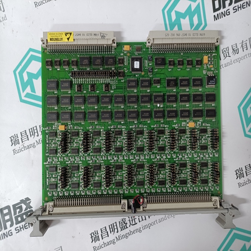
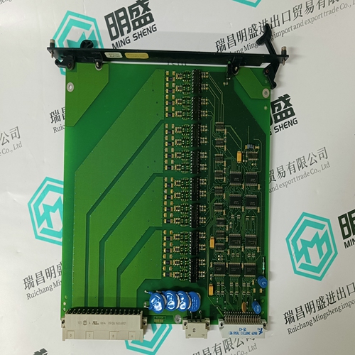
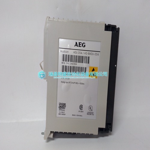
HONEYWELL 51307075-175 CC-TAIX51 module
- Product ID: 51307075-175 CC-TAIX51
- Brand: HONEYWELL
- Place of origin: The United States
- Goods status: new/used
- Delivery date: stock
- The quality assurance period: 365 days
- Phone/WhatsApp/WeChat:+86 15270269218
- Email:stodcdcs@gmail.com
- Tags:HONEYWELL51307075-175CC-TAIX51module
- Get the latest price:Click to consult
HONEYWELL 51307075-175 CC-TAIX51 module
The EIA-530 interface complements the EIA-232-D interface in function. The EIA-530 standard defines the mechanical aspects of this interface, which is used for transmission of serial binary data, both synchronous and asynchronous. It is adaptable to balanced (double-ended) as well as unbalanced (single-ended) signaling and offers the possibility of higher data rates than EIA-232-D with the same DB-25 connector. Table B-4 lists the EIA-530 interconnections that are available at MVME761 serial ports 3 and 4 (J7 and J8 on the board surface) when those ports are configured via serial interface modules as EIA-530 DCE or DTE ports.
Interface Characteristics
In specifying parameters for serial binary data interchange between DTE and DCE devices, the EIA-530 standard assumes the use of balanced lines, except for the Remote Loopback, Local Loopback, and Test Mode lines, which are single-ended. Balanced-line data interchange is generally employed in preference to unbalanced-line data interchange where any of the following conditions prevail: ❏ The interconnection cable is too long for effective unbalanced operation. ❏ The interconnection cable is exposed to extraneous noise sources that may cause an unwanted voltage in excess of ±1V measured differentially between the signal conductor and circuit ground at the load end of the cable, with a 50Ω resistor substituted for the transmitter. ❏ It is necessary to minimize interference with other signals. ❏ Inversion of signals may be required (for example, plus polarity MARK to minus polarity MARK may be achieved by inverting the cable pair).
Proper Grounding
An important subject to consider is the use of ground pins. There are two pins labeled GND. Pin 7 is the signal ground and must be connected to the distant device to complete the circuit. Pin 1 is the chassis ground, but it must be used with care. The chassis is connected to the power ground through the green wire in the power cord and must be connected to be in compliance with the electrical code. The problem is that when units are connected to different electrical outlets, there may be several volts of difference in ground potential. If pin 1 of each device is interconnected with the others via cable, several amperes of current could result. This condition may not only be dangerous for the small wires in a typical cable, but may also produce electrical noise that causes errors in data transmission. That is why Table B-1 and Table B-4 show no connection for pin 1. Normally, pin 7 (signal ground) should only be connected to the chassis ground at one point; if several terminals are used with one computer, the logical place for that point is at the computer. The terminals should not have a connection between the logic ground return and the chassis.


Application industry
Our main products are widely used in metallurgy, oil and gas, glass manufacturing, aluminum, petrochemical, coal mine, paper making and printing, textile printing and dyeing, machinery, electronic manufacturing, automobile manufacturing, tobacco, plastic machinery, electricity, water conservancy, water treatment/environmental protection, municipal engineering, boiler heating, energy, power transmission and distribution, etc.
Superior products
We mainly make spare parts for DCS, PLC, robot control system and large servo system.
Main products: various modules/cards, controllers, touch screens, servo drives.
Advantages: professional off production accessories,
Fast delivery, accurate delivery time,
Main brands include ABB, GE/FANC, FOXBORO, TRICONEX, BENTLY NEVADA, A-B, EMERSON, OVATION, MOTOROLA, XYVOM, HONEYWELL, REXROTH, KUKA, NI, DEIF, Reliance Electric, Yokogawa, WOODWARD, SCHNEIDER, MOOG, PROSOFT and other brands
